Mitsubishi L200. Manual - part 306
TRANSMISSION CONTROL <4A/T>
AUTOMATIC TRANSMISSION
23A-131
TRANSMISSION CONTROL <4A/T>
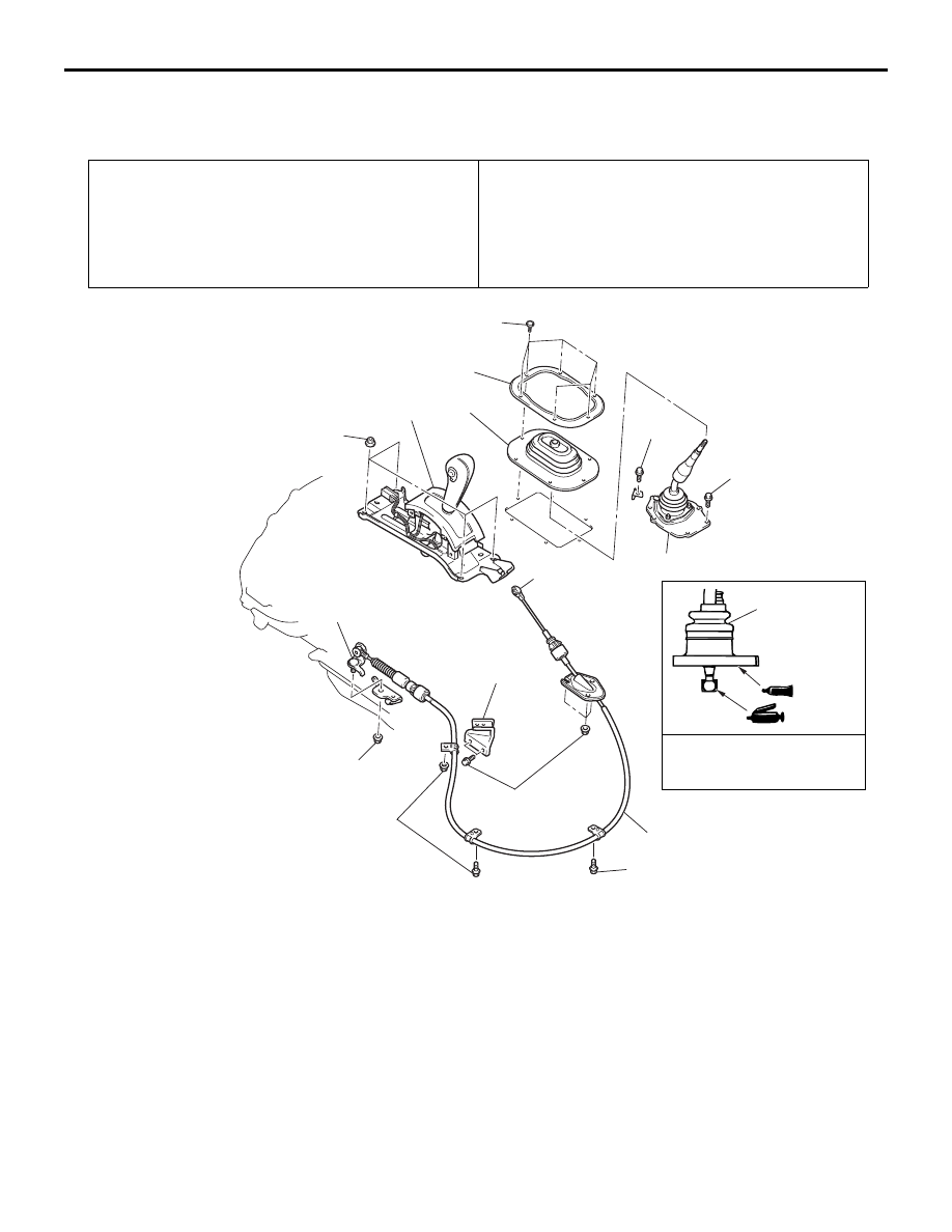
REMOVAL AND INSTALLATION
M1231117900554
Pre-removal Operation
• Move the selector lever to the N range position.
• Front Floor Console Assembly Removal (Refer to
GROUP 52A, Floor Consol Assembly .)
Post-installation Operation
• Front Floor Console Assembly Installation (Refer to
GROUP 52A, Floor Consol Assembly .)
• Transmission Control Cable Adjustment (Refer to
).
• Check that the selector lever is moved to each position
smoothly and correctly.
AC509716AB
1
2
3
4
11 ± 2 N·m
11 ± 2 N·m
11 ± 2 N·m
5
19 ± 3 N·m
11 ± 2 N·m
3.2 ± 0.2 N·m
7
8
19 ± 3 N·m
5
Semi-drying sealant:
3M ATD Part No.8660 or
equivalent
23 ± 4 N·m
6
Selector lever assembly removal
steps
1.
Transmission control cable
connection
2.
Selector lever assembly
Transfer control lever removal
steps <4WD>
3.
Dust cover retaining plate
4.
Dust cover
5.
Transfer control lever assembly
Transmission control cable
assembly removal steps
1.
Transmission control cable
connection
6.
Adjust lever connection
7.
Cable bracket
8.
Transmission control cable
assembly