Mitsubishi L200. Manual - part 267
AK503403AJ
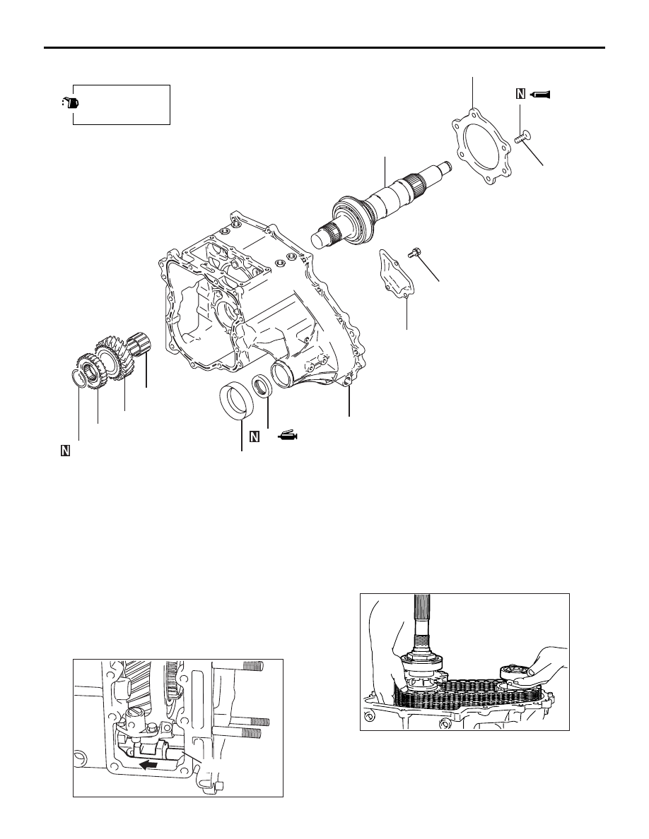
20 ± 2 N·m
Apply gear oil to
all moving parts
before installation.
66
67
68
69
70
71
72
73
74
9.0 ± 1.0 N·m
75
Disassembly steps
>>
D
<<
66. Snap ring
>>
C
<<
67. H-L clutch hub
68. Low speed gear
69. Needle bearing
70. Rear bearing retainer
71. Transfer drive shaft
72. Oil pool cover
73. Dust seal guard
>>
A
<<
74. Oil seal
75. Transfer case
TRANSFER
MANUAL TRANSMISSION OVERHAUL <V5MB1>
22C-53
DISASSEMBLY SERVICE POINTS
<<A>> H-L SHIFT RAIL REMOVAL
AK503405 AB
2-4WD shift rail
1. Fix the H-L shift rail at the high position.
2. Shift the 2-4WD shift rail at the 4WD position.
NOTE: If the 2-4WD shift rail is at the 2WD posi-
tion, the chain cover cannot be removed because
interlock is actuated.
<<B>> REAR OUTPUT SHAFT / CHAIN/FRONT
OUTPUT SHAFT REMOVAL
AK500492
Remove the rear output shaft, chain and front output
shaft as a set.