Mitsubishi L200. Manual - part 257
SPECIAL TOOLS
MANUAL TRANSMISSION OVERHAUL <V5MB1>
22C-13
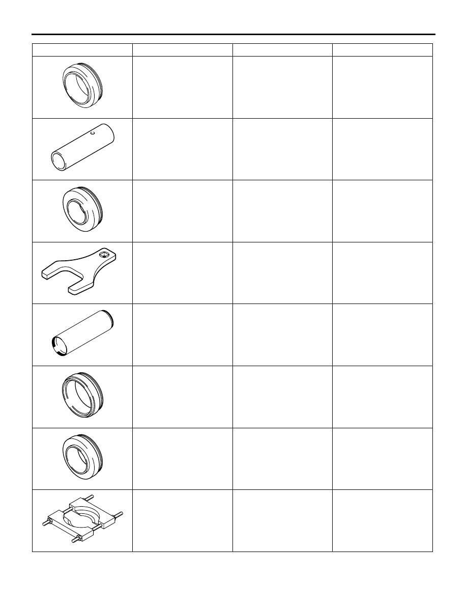
MD998824
Installer adapter (50)
Installation of transfer
input gear bearing
MD998368
Bearing Installer
Installation of
countershaft gear bearing
MD998818
Installer adapter (38)
Installation of
countershaft gear
bearing, front output shaft
bearing
MB991013
power steering lock nut
special spanner
Removal and installation
of output shaft locking nut
MD998814
Installer-200
Use with installer cap and
installer adapter
MD998829
Installer adapter (60)
Installation of rear output
shaft ball bearing and
stopper plate
MD998821
Installer adapter (44)
Installation of clutch hub
and rear output shaft ball
bearing
MD998917
Bearing remover
Removal of rear output
shaft bearing <V5MB1-J-
ND2, NEZ, PD2>
Tool
Number
Name
Use