Mitsubishi L200. Manual - part 252


  Index      Mitsubishi     Mitsubishi L200 - service repair manual 2012 year


Search            


Content   ..  250  251  252  253   ..


Mitsubishi L200. Manual - part 252


OUTPUT SHAFT

MANUAL TRANSMISSION OVERHAUL <R5MB1>

22B-33

<<D>> TRANSMISSION CLUTCH HUB No.2 / 
SYNCHRONIZER SHIFTING KEY No.2 / 
COMPRESSION SPRING / TRANSMISSION HUB 
SLEEVE No.2 / SYNCHRONIZER RING SET No.2 / 
3RD GEAR SUB-ASSEMBLY REMOVAL

AK404020

MD998801

AB

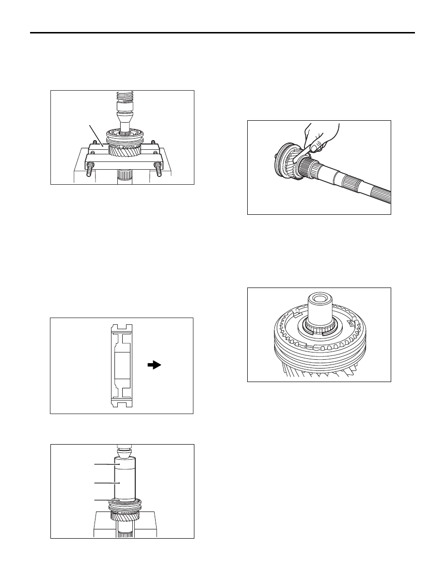
Using special tool Bearing remover (MD998801), 
support the 3rd gear sub-assembly and remove the 
transmission clutch hub No.2, synchronizer shifting 
key No.2, compression spring, the transmission hub 
sleeve No.2, synchronizer ring set and the 3rd gear 
sub-assembly.

REASSEMBLY SERVICE POINTS

>>A<< TRANSMISSION CLUTCH HUB No. 2 / 
SYNCHRONIZER SHIFTING KEY No. 2 / COM-
PRESSION SPRING / TRANSMISSION HUB 
SLEEVE No. 2 / SYNCHRONIZER RING SET No. 2 
/ 3RD GEAR SUB-ASSEMBLY INSTALLATION

AK500607

Installation
direction

AB

1. Check the installation direction of the transmission 

clutch hub No. 2, and put it on the output shaft.

AK404029

AC

MD998812

MD998823

MD998813

2. Using special tools to install the transmission 

clutch hub No. 2, synchronizer shifting key No. 2, 
compression spring, the transmission hub sleeve 
No. 2, synchronizer ring set No. 2 and the 3rd 
gear sub-assembly.

• Installer cap (MD998812)

• Installer-100 (MD998813)

AK500508

Installer adapter (48) (MD998823)

3. Confirm the thrust clearance of the 3rd gear sub-

assembly is within the standard value.

Standard value: 0.10 

 0.25 mm

Limit: 0.25 mm

>>B<< SHAFT SNAP RING INSTALLATION

AK404019

1. Select a shaft snap ring to secure the standard 

clearance between the transmission clutch hub 
No.2 and the output shaft.

Standard value: 0 

 0.1 mm

2. Install the selected snap ring.

OUTPUT SHAFT

MANUAL TRANSMISSION OVERHAUL <R5MB1>

22B-34

>>C<< REVERSE GEAR / SYNCHRONIZER 
SHIFTING KEY No. 1 / COMPRESSION SPRING / 
TRANSMISSION CLUTCH No. 1 HUB /    
SYNCHRONIZER RING SET No. 1 / 2ND GEAR 
SUB-ASSEMBLY INSTALLATION

AK500608

Installation
direction

AB

1. Check the installation direction of the reverse 

gear, and put it on the output shaft.

AK404030

AC

MD998812

MD998823

MD998813

MD998814

2. Using special tools to install the reverse gear, 

synchronizer shifting key No. 1, compression 
spring, the transmission clutch No. 1 hub, 
synchronizer ring set No. 1 and the 2nd gear sub-
assembly.

• Installer cap (MD998812)

• Installer-100 (MD998813)

• Installer-200 (MD998814)

AK404032

Installer adapter (48) (MD998823)

3. Confirm the thrust clearance of the 2nd gear sub-

assembly is within the standard value.

Standard value: 0.10 

 0.25 mm

Limit: 0.25 mm

>>D<< SHAFT SNAP RING INSTALLATION

AK404031

1. Select a snap ring to secure the standard 

clearance between the transmission clutch No. 1 
hub and the output shaft. 

Standard value: 0 

 0.1 mm

2. Install the selected snap ring.

>>E<< RADIAL BALL BEARING / 1ST GEAR SUB-
ASSEMBLY INSTALLATION

AK500606AB

Installation
direction

1. Check the installation direction of the radial ball 

bearing, and put it on the output shaft.

CAUTION

Never push on the sealing area when installing.

AK404038

AB

MD998812

MD998823

MD998814

2. Using special tools to install the radial ball bearing 

and the 1st gear sub-assembly.

• Installer cap (MD998812)

• Installer-200 (MD998814)

• Installer adapter (48) (MD998823)

AK500513

OUTPUT SHAFT

MANUAL TRANSMISSION OVERHAUL <R5MB1>

22B-35

3. Confirm the thrust clearance of the 1st gear sub-

assembly is within the standard value.

Standard value: 0.20 

 0.45 mm

Limit: 0.45 mm

>>F<< 5TH GEAR INSTALLATION

AK500609

Installation
direction

AB

1. Check the installation direction of the 5th gear, 

and put it on the output shaft.

AK404039

AB

MD998812

MD998823

MD998814

2. Using special tools to install the 5th gear.

• Installer cap (MD998812)

• Installer-200 (MD998814)

• Installer adapter (48) (MD998823)

>>G<< SHAFT SNAP RING INSTALLATION

AK404040

1. Select a shaft snap ring to secure the standard 

clearance between the 5th gear and the output 
shaft

Standard value: 0 

 0.1 mm

2. Install the selected snap ring.

INSPECTION

M1222002300261

SYNCHRONIZER RING

CAUTION

When any of the outer ring, inner ring or cone 
has to be replaced, replace them as a set.

AK500672AB

1. Check to ensure that the clutch gear tooth surface 

and cone surface are not damaged and broken.

AK500603

2. After applying oil to the taper portion on each 

gear, press and fit the synchronizer ring by hand. 
Confirm the synchronizer ring cannot be rotated.

AK404022

OUTPUT SHAFT

MANUAL TRANSMISSION OVERHAUL <R5MB1>

22B-36

3. Using the thickness gauge, check the clearance 

between the synchronizer ring and the gear.

Gear

Standard value mm

Limit mm

1st

0.65 

− 1.75

0.65

2nd

0.65 

− 1.75

0.65

3rd

0.65 

− 1.75

0.65

HUB SLEEVE AND SHIFT FORK

CAUTION

When any of the hub sleeve or shift fork has to be 
replaced, replace them as a set.

AK404023

Using the thickness gauge, check the clearance 
between the sleeve and the shift fork.

sleeve

Standard 
value mm

Limit mm

No.1

0.15 

− 0.41

0.41

No.2

0.15 

− 0.35

0.35

No.3

0.26 

− 0.84

0.84

SYNCHRONIZER SLEEVE AND HUB
1. Combine the synchronizer sleeve and hub, and 

check that they slide smoothly.

2. Check that the sleeve is free from damage at its 

inside splines ends.

NEEDLE ROLLER BEARING
1. Combine the needle roller bearing with the output 

shaft and gear, and check that it rotates smoothly 
without noise or play.

2. Check the needle roller bearing cage for 

deformation.

SYNCHRONIZER KEYS

AK500680AB

Check the synchronizer hub contact surfaces of each 
synchronizer key for damage and excessive wear.

COMPRESSION SPRINGS
Check the compression springs for loss of tension, 
deformation, and breakage.

OUTPUT SHAFT

AK404024

AB

A

B

C

1. Using the micrometer, check the outer shape of 

the needle roller bearing race.

Measurement 
part

Standard value mm Limit mm

A

37.984 

− 38.000

37.984

B

46.984 

− 47.000

46.984

C

38.979 

− 38.995

38.979


Content   ..  250  251  252  253   ..