Mitsubishi L200. Manual - part 250


  Index      Mitsubishi     Mitsubishi L200 - service repair manual 2012 year


Search            


Content   ..  248  249  250  251   ..


Mitsubishi L200. Manual - part 250


AK500527

AB

TRANSMISSION

MANUAL TRANSMISSION OVERHAUL <R5MB1>

22B-25

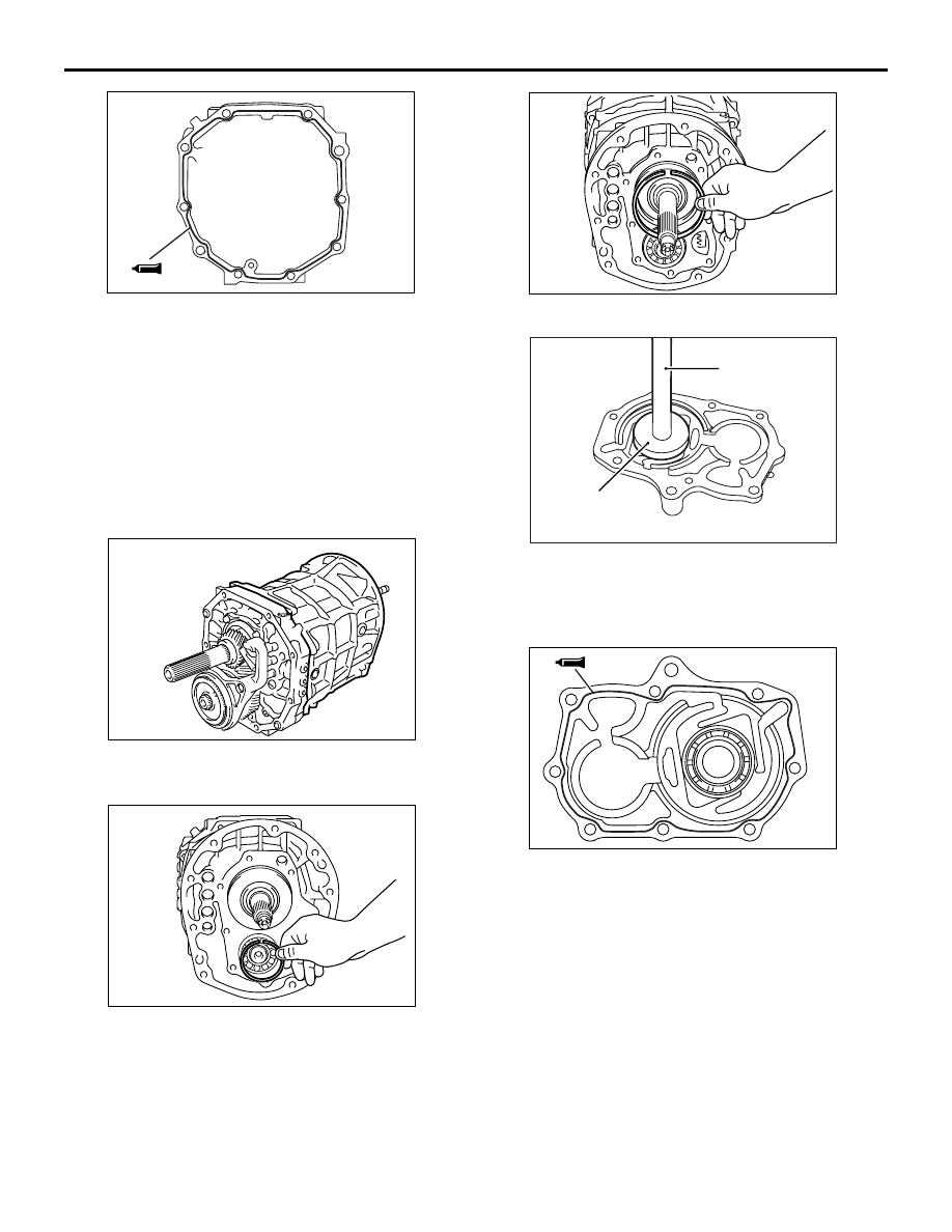
48.Completely degrease the FIPG-applied surface 

so that water and oil including the old sealant 
cannot adhere to the surface coated with the 
sealant.
Never touch the degreased surface by hand. 

49.Apply a 1.2 mm diameter bead of liquid gasket to 

the intermediate plate mounting surface of the 
transmission case sub-assembly.

Special sealant: Mitsubishi genuine sealant 
Part No. MD974421 or equivalent

AK701366

50.Install the transmission case sub-assembly to the 

intermediate plate.

AK403783

51.Install the snap ring to the cylindrical roller 

bearing.

AK403782

52.Install the snap ring to the radial ball bearing.

AK600320

MB990938

MB990929

AB

53.Using special tool, install the oil seal to the front 

bearing retainer.

• Installer adapter (MB990929)

AK403775

AB

Installer bar (MB990938)

54.Completely degrease the FIPG-applied surface 

so that water and oil including the old sealant 
cannot adhere to the surface coated with the 
sealant.
Never touch the degreased surface by hand. 

55.Apply a 1.2 mm diameter bead of liquid gasket to 

the transmission case sub-assembly mounting 
surface of the front bearing retainer sub-assembly 
with seal.

Special sealant: Mitsubishi genuine sealant 
Part No. MD974421 or equivalent

AK403774

TRANSMISSION

MANUAL TRANSMISSION OVERHAUL <R5MB1>

22B-26

CAUTION

Do not damage to the oil seal lip during the 
installation.
56.Apply sealant to the threads. Install the front 

bearing retainer to the transmission case sub-
assembly and tighten the bolts to the specified 
torque of 16.5 

± 5.0 N⋅m.

Special sealant: Mitsubishi genuine sealant 
Part No. MD974421 or equivalent

NOTE: The new bolt does not require sealant 
application as it is precoated with sealant.

AK403781

57.Install the reverse restrict pin assembly to the 

extension housing sub-assembly.

AK604897AB

58.Install the slotted spring pin to the reverse restrict 

pin assembly.

AK604896

AB

59.Apply sealant to the threads. Tighten the straight 

screw plug with head to the specified torque of 
18.5 

± 5.5 N⋅m.

Special sealant: Mitsubishi genuine sealant 
Part No. MD974421 or equivalent

NOTE: The new bolt does not require sealant 
application as it is precoated with sealant.

AK403777

60.Install the oil receiver pipe into the extension 

housing sub-assembly.

AK500527

AB

61.Completely degrease the FIPG-applied surface 

so that water and oil including the old sealant 
cannot adhere to the surface coated with the 
sealant.
Never touch the degreased surface by hand. 

62.Apply a 1.2 mm diameter bead of liquid gasket to 

the intermediate plate mounting surface of the 
extension housing sub-assembly.

Special sealant: Mitsubishi genuine sealant 
Part No. MD974421 or equivalent

AK604895

Wiring harness 
clamp bracket

Wiring 
harness 
clamp 
bracket

AB

TRANSMISSION

MANUAL TRANSMISSION OVERHAUL <R5MB1>

22B-27

63.Install the extension housing sub-assembly. 

Install the wiring harness clamp bracket (3 places) 
and tighten the bolts to the specified torque of 37 
± 11 N⋅m.

AK500816

64.Install the vehicle speed sensor and tighten the 

bolts to the specified torque of 11 

± 1 N⋅m. 

AK500460AB

CAUTION

Install the bolt and washer (with sealant) to the 
position having the arrow as shown in the illus-
tration.
65.Install the clutch housing into the transmission 

case sub-assembly. Tighten the bolt with washer 
to the specified torque of 36 

± 7 N⋅m (7 places). 

Tighten the bolt with washer (with sealant) to the 
specified torque of 34 

± 6 N⋅m (2 places). 

Special sealant: Mitsubishi genuine sealant 
Part No. MD974421 or equivalent

AK704967

AC

Back-up lamp switch
assembly

Shift position switch
assembly

<R5MB1-J-NC>

AK704968

AD

Back-up lamp switch
assembly

<R5MB1-J-ND1>

66.Tighten the shift position switch assembly of 34 

± 

5 N

⋅m. <R5MB1-J-NC>

67.Tighten the back-up lamp switch assembly and of 

44 

± 9 N⋅m.

INSPECTION

M1222001100491

BACK-UP LAMP SWITCH

AK500505

Check for the continuity between the connector ter-
minals.

Switch 
condition

Connector 
terminals

Continuity

Switch end 
pressed

− 2

Conductive

Switch end 
released

− 2

Open

TRANSMISSION

MANUAL TRANSMISSION OVERHAUL <R5MB1>

22B-28

SHIFT POSITION SWITCH 

AK501632

Check for the continuity between the connector ter-
minals.

Switch 
condition

Connector 
terminals

Continuity

Switch end 
pressed

− 2

Open

Switch end 
released

− 2

Conductive

SYNCHRONIZER SLEEVE AND HUB

1. Combine the synchronizer sleeve and hub, and 

check that they slide smoothly.

2. Check that the sleeve is free from damage at its 

inside splines ends.

3. Using the thickness gauge, check the clearance 

between the synchronizer ring and the gear.

Standard value: 0.52 

 1.88 mm

Limit: 0.52 mm

NEEDLE ROLLER BEARING

1. Combine the needle roller bearing with the shaft 

and gear, and check that it rotates smoothly 
without noise or play.

2. Check the needle roller bearing cage for 

deformation.

COUNTER SHAFT GEAR No.5

THRUST CLEARANCE
Inspect the thrust clearance of counter shaft gear 
No.5.

Standard value: 0.10 

 0.35 mm

Limit: 0.35 mm

RADIAL CLEARANCE
1. Fix the output shaft in a vice.
2. Inspect the radial clearance of counter shaft gear 

No.5.

Standard value: 0.015 

 0.068 mm

Limit: 0.068 mm

INSIDE DIAMETER

AK404027

Using the cylinder gauge, check the inside diameter 
of the counter shaft gear No.5.

Standard value: 38.015 

 38.040 mm

Limit: 38.040 mm


Content   ..  248  249  250  251   ..