Mitsubishi L200. Manual - part 243


  Index      Mitsubishi     Mitsubishi L200 - service repair manual 2012 year


Search            


Content   ..  241  242  243  244   ..


Mitsubishi L200. Manual - part 243


TRANSMISSION ASSEMBLY

MANUAL TRANSMISSION (FR)

22A-9

TRANSMISSION ASSEMBLY

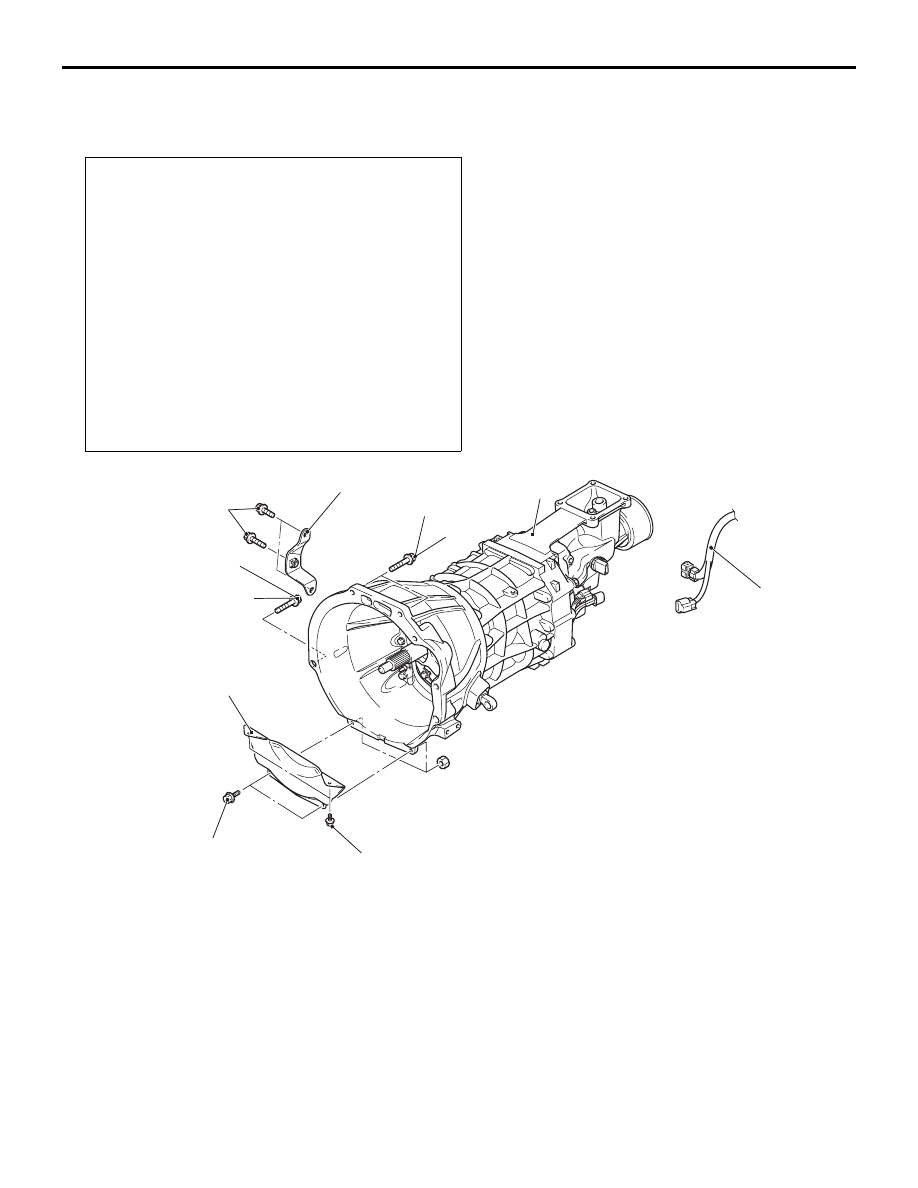
REMOVAL AND INSTALLATION <2WD>

M1221102400488

Pre-removal and Post-installation Operations
• Transmission Control Lever Assembly Removal and 

Installation (Refer to 

P.22A-7

).

• Transmission Oil Draining and Refilling (Refer to 

P.22A-

3

).

• Under Skid Plate and Engine Room Under Cover 

Removal and Installation.

• Propeller Shaft Assembly Removal and Installation (Refer 

to GROUP 25 

− Propeller Shaft ).

• Clutch Release Cylinder Assembly and Clutch Damper 

Assembly Removal and Installation (Disconnect the con-

nection with transmission only and do not disconnect the 

clutch line.).

• Starter Assembly Removal and Installation (Refer to 

GROUP 16 

− Starter Motor Assembly ).

• No.2 Crossmember Assembly and Transmission Mount 

Insulator Assembly Removal and Installation (Refer to 

GROUP 32 

− Rear Engine Mounting ).

AC807940

1

AC

2

4

5

6

25 ± 4 N·m

48 ± 6 N·m

48 ± 6 N·m

3

9.0 ± 1.0 N·m

11 ± 1 N·m

Removal steps 

1.

Transmission harness connector 
connection

Support the transmission with a 
transmission jack

2.

Bell housing cover

3.

Transmission assembly lower part 
coupling bolts

4.

Front exhaust pipe bracket

5.

Transmission assembly upper part 
coupling bolts

6.

Transmission assembly

Removal steps (Continued)

TRANSMISSION ASSEMBLY

MANUAL TRANSMISSION (FR)

22A-10

REMOVAL AND INSTALLATION <4WD>

M1221102400499

Pre-removal and Post-installation Operations
• Transmission Control Lever Assembly and Transfer Con-

trol Lever Assembly Removal and Installation (Refer to 

P.22A-7

).

• Transmission Oil Draining and Refilling (Refer to 

P.22A-

3

).

• Transfer Oil Draining and Refilling (Refer to 

P.22A-4

).

• Under Skid Plate and Engine Room Under Cover 

Removal and Installation (Refer to GROUP 51 

− Under 

Cover ).

• Front and Rear Propeller Shaft Removal and Installation 

(Refer to GROUP 25 ).

• Front Exhaust Pipe Removal and Installation (Refer to 

GROUP 15 

− Front Exhaust Pipe and Main Muffler .)

• Clutch Release Cylinder Assembly and Clutch Damper 

Assembly Removal and Installation (Disconnect the con-

nection with transmission only and do not disconnect the 

clutch line.) (Refer to GROUP 21A 

− Clutch Release Cyl-

inder Assembly ).

• Starter Assembly Removal and Installation (Refer to 

GROUP 16 

− Starter Motor Assembly ).

• Transfer Mount Bracket Assembly Removal and Installa-

tion (Refer to GROUP 32 

− Transfer Mounting ).

• No.2 Crossmember Assembly and Transmission Mount 

Insulator Assembly Removal and Installation (Refer to 

GROUP 32 

− Rear Engine Mounting ).

AC809607AB

1

2

11 ± 1 N·m

9.0 ± 1.0 N·m

3

4

5

6

48 ± 6 N·m

25 ± 4 N·m

48 ± 6 N·m

Removal steps 

1.

Transmission harness connector 
connection

Support the transmission with a 
transmission jack

2.

Bell housing cover

3.

Transmission assembly lower part 
coupling bolts

4.

Front exhaust pipe bracket

5.

Transmission assembly upper part 
coupling bolts

6.

Transmission assembly

Removal steps (Continued)

4WD INDICATOR-ECU

MANUAL TRANSMISSION (FR)

22A-11

4WD INDICATOR-ECU

REMOVAL AND INSTALLATION

M1221102900029

AC509527AB

1

<Vehicles with LHD>

<Vehicles with RHD>

Removal steps 

Glove Box Cover (Refer to GROUP 
52A, Instrument Panel Assembly ).

1.

4WD indicator-ECU 

INSPECTION

M1221101200157

4WD INDICATOR-ECU

AC504329AB

A

VIEW A

1. Measure the voltage with the control unit and 

harness still connected.

2. Earth terminal (8) and then measure the terminal 

voltage.

EASY SELECT 4WD

Terminal 
No.

Inspection item

Ignition switch Transfer shift position

Terminal voltage

1

Free wheel engage switch

ON

2H

System voltage

4H

*1

1 V or less

2

4WD detection switch

ON

2H

System voltage

4H, 4L

1 V or less

3

Ignition switch

ON

System voltage

OFF

1 V or less

6

High/low detection switch

ON

While switching between 
4H and 4L

System voltage

2H, 4H, 4L

1 V or less

4WD INDICATOR-ECU

MANUAL TRANSMISSION (FR)

22A-12

NOTE: 

.

*1

: When vehicle has been moved once.

*2

: Shift the lever from 4H to 2H, and then turn the ignition switch to OFF and then back to ON.

<SUPER SELECT 4WD>

Terminal 
No.

Inspection item

Ignition switch Transfer shift position

Terminal voltage

1

Free wheel engage switch

ON

2H

System voltage

4H

*1

1 V or less

2

4WD operation detection 
switch

ON

2H

System voltage

4H, 4HLc, 4LLc

1 V or less

3

Ignition switch

ON

System voltage

OFF

1 V or less

4

Centre differential lock indicator 
lamp

ON

4H

1 V or less

4HLc

System voltage

5

Rear wheel indicator lamp

ON

While switching between 
4HLc and 4LLc

1 V or less

2H, 4H, 4HLc, 4LLc

System voltage

6

High/low detection switch

ON

While switching between 
4HLc and 4LLc

System voltage

2H, 4H, 4HLc, 4LLc

1 V or less

7

Centre differential lock 
operation detection switch

ON

4HLc

1 V or less

4H

*2

System voltage

9

Centre differential lock 
detection switch

ON

4HLc

1 V or less

4H

*2

System voltage

10

Front wheel indicator lamp

ON

While switching between 
4HLc and 4LLc

1 V or less

4H, 4HLc, 4LLc

System voltage

NOTE: 

.

*1

: When vehicle has been moved once.

*2

: Shift the lever from 4HLc to 4H, and then turn the ignition switch to OFF and then back to ON.

7

Free wheel clutch changeover 
solenoid valve

ON

4H, 4L

1 V or less

2H

*2

System voltage

10

4WD indicator lamp

ON

2H

1 V or less

4H, 4L

System voltage

Terminal 
No.

Inspection item

Ignition switch Transfer shift position

Terminal voltage


Content   ..  241  242  243  244   ..