Mitsubishi L200. Manual - part 242


  Index      Mitsubishi     Mitsubishi L200 - service repair manual 2012 year


Search            


Content   ..  240  241  242  243   ..


Mitsubishi L200. Manual - part 242


ON-VEHICLE SERVICE

MANUAL TRANSMISSION (FR)

22A-5

Check the continuity between terminals of the black 
connector and earth indicated in the illustration.

Transfer lever position Specified condition
2H

Open circuit

4H, 4L

Continuity (Less than 2 
Ω)

HIGH/LOW DETECTION SWITCH 
CONTINUITY CHECK <EASY SELECT 
4WD>

M1221102800141

AC503107AB

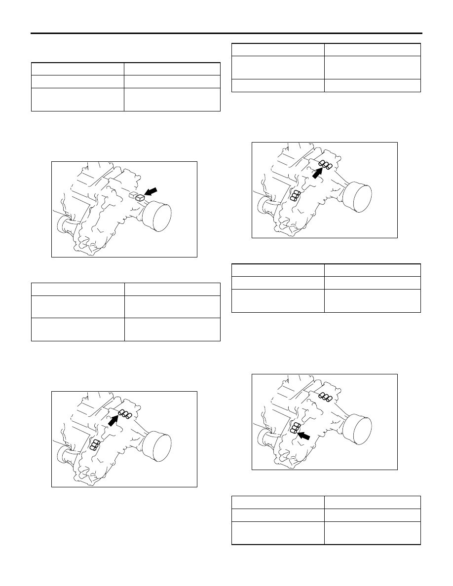
Check the continuity between terminals of the grey 
connector and earth indicated in the illustration.

Transfer lever position Specified condition
While switching between 
4H and 4L

Open circuit

2H, 4H, 4L

Continuity (Less than 2 
Ω)

CENTRE DIFFERENTIAL LOCK 
DETECTION SWITCH CONTINUITY 
CHECK <SUPER SELECT 4WD>

M1221103100112

AC509434AC

Check the continuity between terminals of the brown 
connector and earth indicated in the illustration.

Transfer lever position Specified condition
4HLc and 4LLc

Continuity (Less than 2 
Ω)

2H and 4H

Open circuit

2WD/4WD DETECTION SWITCH 
CONTINUITY CHECK <SUPER SELECT 
4WD>

M1221103200119

AC509434AB

Check the continuity between terminals of the black 
connector and earth indicated in the illustration.

Transfer lever position Specified condition
2H

Open circuit

4H, 4HLc and 4LLc

Continuity (Less than 2 
Ω)

CENTRE DIFFERENTIAL LOCK 
OPERATION DETECTION SWITCH 
CONTINUITY CHECK <SUPER SELECT 
4WD>

M1221103300075

AC509434AD

Check the continuity between terminals of the black 
connector and earth indicated in the illustration.

Transfer lever position Specified condition
2H and 4H

Open circuit

4HLc and 4LLc

Continuity (Less than 2 
Ω)

ON-VEHICLE SERVICE

MANUAL TRANSMISSION (FR)

22A-6

4WD OPERATION DETECTION SWITCH 
CONTINUITY CHECK <SUPER SELECT 
4WD>

M1221103400038

AC509434AF

Check the continuity between terminals of the brown 
connector and earth indicated in the illustration.

Transfer lever position Specified condition
2H

Open circuit

4H, 4HLc and 4LLc

Continuity (Less than 2 
Ω)

HIGH/LOW DETECTION SWITCH 
CONTINUITY CHECK <SUPER SELECT 
4WD>

M1221102800152

AC509434AG

Check the continuity between terminals of the white 
connector and earth indicated in the illustration.

Transfer lever position Specified condition
While switching between 
4HLc and 4LLc

Open circuit

2H, 4H, 4HLc and 4LLc Continuity (Less than 2 

Ω)

4LLc SWITCH CONTINUITY CHECK 
<HIGH POWER ENGINE>

M1221144400024

AC509434AE

Check the continuity between terminals of the white 
connector and earth indicated in the illustration.

Transfer lever position Specified condition
2H, 4H, and 4HLc

Continuity (Less than 2 
Ω)

4LLc

Open circuit

TRANSMISSION CONTROL

MANUAL TRANSMISSION (FR)

22A-7

TRANSMISSION CONTROL

REMOVAL AND INSTALLATION

M1221102200116

<2WD>

Pre-removal Operation
Move the transmission control lever to the Neutral position.

Post-installation Operation
Check that the transmission control lever is moved to each 
position smoothly and correctly.

AC609267AB

1

2

3

4

5

3.2 ± 0.2 N·m

19 ± 3 N·m

N

4

Semi-drying sealant:
  3M ATD Part No.8660 or 
  equivalent

5

Removal steps 

1.

Shift knob

Front floor console assembly (Refer 
to GROUP 52A, Floor Consol 
Assembly .)

2.

Dust cover retaining plate

3.

Dust cover

4.

Transmission control lever assembly

5.

Gasket

Removal steps (Continued)

TRANSMISSION CONTROL

MANUAL TRANSMISSION (FR)

22A-8

<4WD>

Pre-removal Operation
Move the transmission control lever and transfer control 
lever to the following positions.
• Transmission control lever: Neutral

• Transfer control lever: 4H

Post-installation Operation
Check that the transmission control lever and the transfer 
control lever are moved to each position smoothly and 
correctly.

AC509473AB

1

2

3

4

5

6

3.2 ± 0.2 N·m

19 ± 3 N·m

19 ± 3 N·m

Semi-drying sealant: 
  3M ATD Part No.8660 or equivalent

7

7

Removal steps 

1.

Shift knob

>>

A

<< 2.

Sleeve

3.

Transfer shift lever knob

Front floor console assembly 
<Vehicles with front floor consol 
assembly> (Refer to GROUP 52A, 
Floor Consol Assembly .)

4.

Dust cover retaining plate

5.

Control lever cover <Vehicles without 
front floor consol assembly>

6.

Dust cover

7.

Transmission control lever assembly 
and transfer control lever assembly

INSTALLATION SERVICE POINT

>>A<< SLEEVE INSTALLATION

AC503137AB

Shift knob

Sleeve

Install the sleeve with its groove facing to the direc-
tion shown in the figure, and then install the shift 
knob.


Content   ..  240  241  242  243   ..