Mitsubishi L200. Manual - part 238
CLUTCH PEDAL
CLUTCH
21A-4
CLUTCH PEDAL
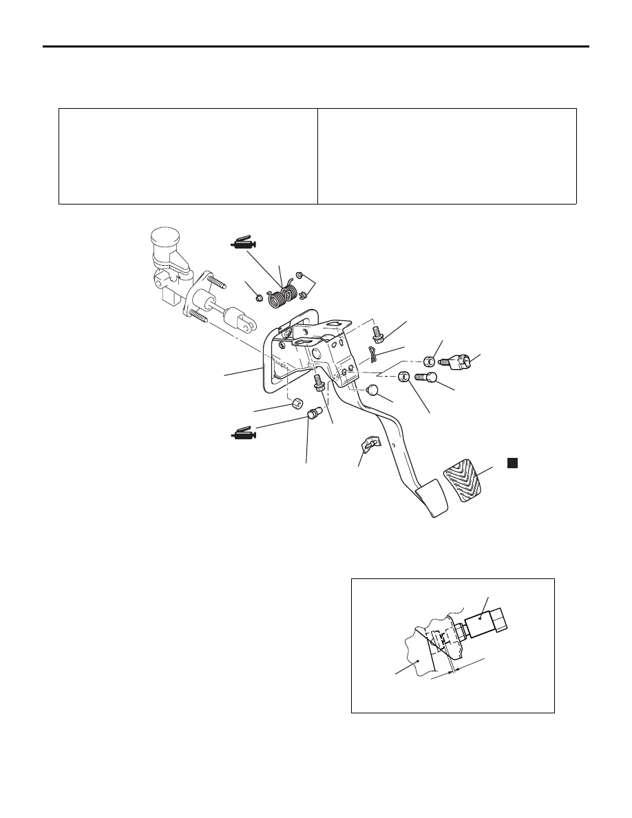
REMOVAL AND INSTALLATION
M1211001601008
Pre-removal Operation
• Lower Panel Assembly Removal (Refer to GROUP 52A −
Instrument Panel Assembly ).
• Drivers side under cover <Except vehicles Single cab>
Removal (Refer to GROUP 52A
− Instrument Panel
Assembly ).
• ETACS-ECU Removal. <LHD>
Post-installation Operation
• ETACS-ECU Installation. <LHD>
• Drivers side under cover <Except vehicles Single cab>
Installation (Refer to GROUP 52A
− Instrument Panel
Assembly ).
• Lower Panel Assembly Installation (Refer to GROUP 52A
− Instrument Panel Assembly ).
• Clutch Pedal Adjustment (Refer to
AC900934
7
1
2
3
13 ± 2 N·m
AB
12 ± 2 N·m
9
6
8
12 ± 2 N·m
10
7
13 ± 2 N·m
13 ± 2 N·m
4
5
<Vehicles with
cruise control>
<Vehicles without
cruise control>
N
Removal steps
1.
Snap pin
2.
Clevis pin
3.
Clutch pedal assembly
4.
Adjusting bolt <Vehicles without
cruise control>
>>
A
<<
5.
Clutch switch <Vehicles with cruise
control>
6.
Return spring
7.
Bushing
8.
Stopper
9.
Pedal stopper
10. Pedal pad
INSTALLATION SERVICE POINT
>>A<< CLUTCH SWITCH <VEHICLES WITH
CRUISE CONTROL> INSTALLATION
AC309757
AC
Clutch pedal
Clutch switch
0.5 – 1.0 mm
Install the clutch switch at the specified dimension
when the clutch pedal is released.