Mitsubishi L200. Manual - part 214


  Index      Mitsubishi     Mitsubishi L200 - service repair manual 2012 year


Search            


Content   ..  212  213  214  215   ..


Mitsubishi L200. Manual - part 214


AC712053

Stopper end

AB

Stopper

Bulge

Hose clamp

5 ± 1 mm

Intercooler  
air pipe

Intercooler  
air hose

AC712054

Stopper end

AB

Stopper

Bulge

Hose clamp

Intercooler 
assembly

5 ± 1 mm

Intercooler 
outlet 
air hose

AC804006

Stopper end

AB

Hose clamp

4 ± 1 mm

Intercooler 
outlet 
air hose

Throttle body 
assembly

Stopper

Bulge

AC804007AB

Hose clamp

4 ± 1 mm

Bulge

Stopper

Intercooler 
inlet air 
hose

Stopper end

Turbocharger 
assembly

INTERCOOLER

INTAKE AND EXHAUST

15-11

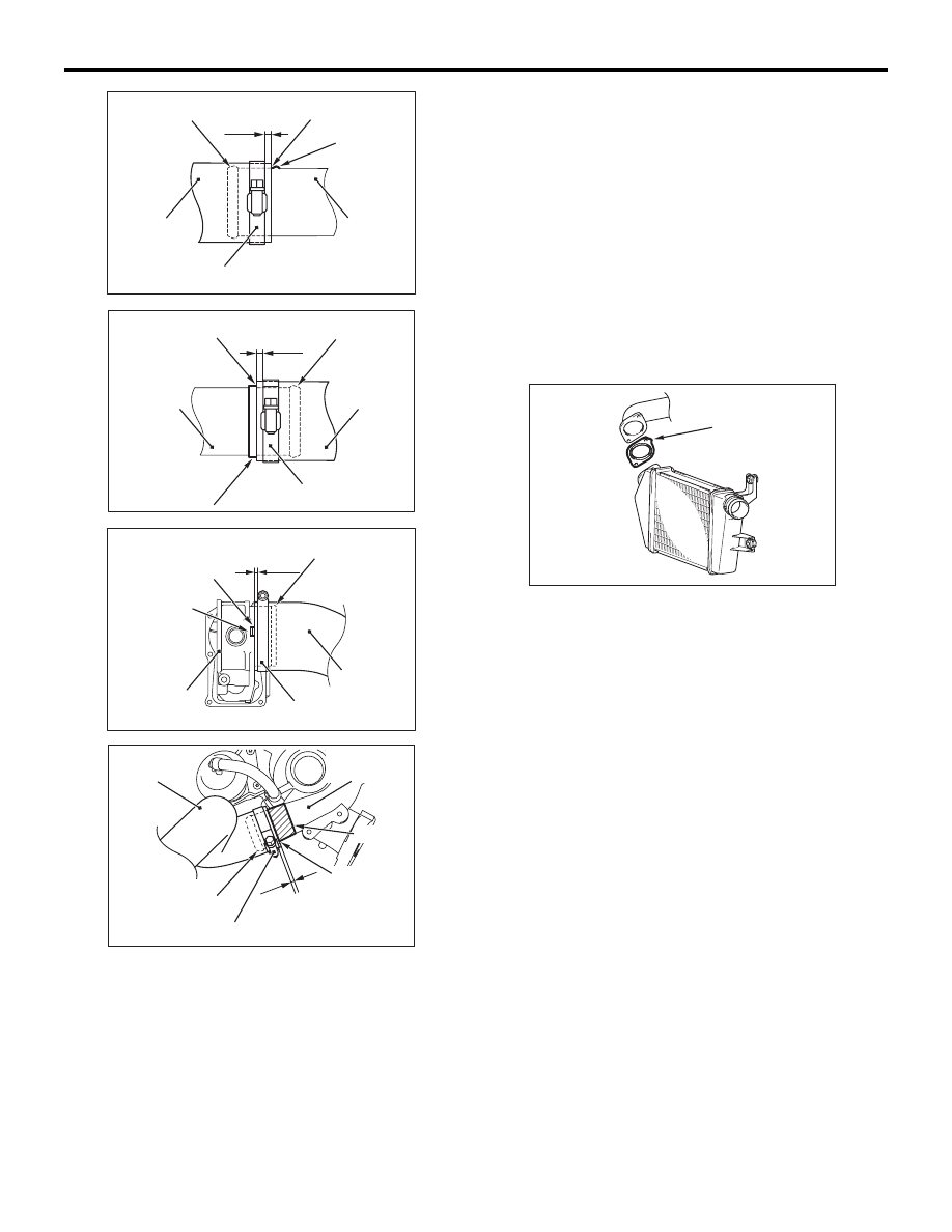
7. Insert intercooler air hose to stopper end and not 

overlap with stopper.

8. Place the hose clamp as shown in the figure so 

that it does not overlap with the bulge and the 
stopper end. When installing the hose clamp to 
the intercooler air pipe or intercooler assembly, 
set the hose clamp 5 

± 1 mm away from the 

stopper end. When installing the hose clamp to 
the throttle body assembly or turbocharger 
assembly, set the hose clamp 4 

± 1 mm away 

from the stopper end.

>>B<< INTERCOOLER INLET AIR PIPE GASKET 
INSTALLATION

AC504286AC

Protrusion

Install the intercooler inlet air pipe gasket as its pro-
trusion is in the direction shown.

INTERCOOLER

INTAKE AND EXHAUST

15-12

REMOVAL AND INSTALLATION <Euro5>

M1151002401219

CAUTION

• Degrease the air hose and air pipe by isopropyl alcohol, parts cleaner (MZ100387) or equivalent.
• As for the parts cleaner, use the petroleum cleaner whose major component is aliphatic hydrocar-

bon.

Pre-removal Operation
• Air Cleaner Intake Duct Removal (Refer to 

P.15-6

).

Post-installation Operation
• Air Cleaner Intake Duct Installation (Refer to 

P.15-6

).

AC804002AB

4

1

2

7

8

6

5

N

12 ± 2 N·m

3

7.0 ± 1.0 N·m

6.0 ± 1.0 N·m

9.0 ± 1.0 N·m

6.0 ± 1.0 N·m

6.0 ± 1.0 N·m

18 ± 2 N·m

6.0 ± 1.0 N·m

6.0 ± 1.0 N·m

Removal steps 

>>

A

<<

1.

Intercooler inlet air hose

>>

A

<<

2.

Intercooler outlet air hose

Front bumper reinforcement 
(Refer to GROUP 51 

− Front 

Bumper Assembly ).

3.

Intercooler inlet air pipe and 
intercooler assembly

>>A<<

4.

Intercooler inlet air pipe

>>

B

<<

5.

Intercooler inlet air pipe gasket

6.

Intercooler assembly

>>

A

<<

7.

Intercooler outlet air hose

>>

A

<<

8.

Intercooler outlet air pipe

Working area should be airy and kept from flame.

INSTALLATION SERVICE POINTS

>>A<< INTERCOOLER OUTLET AIR PIPE/INTER-
COOLER OUTLET AIR HOSE/INTERCOOLER 
INLET AIR PIPE/INTERCOOLER OUTLET AIR 
HOSE/INTERCOOLER INLET AIR HOSE INSTAL-
LATION
1. If the oil adheres to the insertion area of the 

intercooler air hose or the intercooler air pipe, 
degrease it.

ACB00692AB

Matching 
marks

Matching 
marks

Intercooler 
outlet air hose

Intercooler 
inlet air hose

Intercooler 
outlet air pipe

Throttle body 
assembly

Turbocharger 
assembly

Matching 
mark

Intercooler 
inlet air pipe

Intercooler 
outlet air hose

Matching 
mark

ACB00693AB

Matching 
marks

Intercooler 
outlet air hose

Intercooler 
outlet air pipe

Intercooler 
outlet air hose

Matching 
marks

Intercooler 
assembly

INTERCOOLER

INTAKE AND EXHAUST

15-13

INTERCOOLER

INTAKE AND EXHAUST

15-14

2. Install the intercooler air hose to the intercooler air 

pipe with the matching marks aligned as shown in 
the figure.

3. When installing the intercooler air hose to the 

throttle body assembly or the turbocharger 
assembly, install the intercooler air hose with its 
matching mark located as shown in the figure.

AC712053

Stopper end

AB

Stopper

Bulge

Hose clamp

5 ± 1 mm

Intercooler  
air pipe

Intercooler  
air hose

AC712054

Stopper end

AB

Stopper

Bulge

Hose clamp

Intercooler 
assembly

5 ± 1 mm

Intercooler 
outlet 
air hose

AC804006

Stopper end

AB

Hose clamp

4 ± 1 mm

Intercooler 
outlet 
air hose

Throttle body 
assembly

Stopper

Bulge

ACB00694AB

Hose clamp

Bulge

Intercooler 
inlet air 
hose

Turbocharger assembly

4 ± 1 mm

Stopper end

Stopper

4. Insert intercooler air hose to stopper end and not 

overlap with stopper.

5. Place the hose clamp as shown in the figure so 

that it does not overlap with the bulge and the 
stopper end. When installing the hose clamp to 
the intercooler air pipe or intercooler assembly, 
set the hose clamp 5 

± 1 mm away from the 

stopper end. When installing the hose clamp to 
the throttle body assembly or turbocharger 
assembly, set the hose clamp 4 

± 1 mm away 

from the stopper end.

>>B<< INTERCOOLER INLET AIR PIPE GASKET 
INSTALLATION

AC504286AC

Protrusion

Install the intercooler inlet air pipe gasket as its pro-
trusion is in the direction shown.


Content   ..  212  213  214  215   ..