Mitsubishi L200. Manual - part 212
SPECIAL TOOLS
INTAKE AND EXHAUST
15-3
SPECIAL TOOLS
M1151000601842
Tool
Number
Name
Use
MB991910
MB991826
MB991955
MB991911
MB991824
MB991827
MB991825
A
B
C
D
E
F
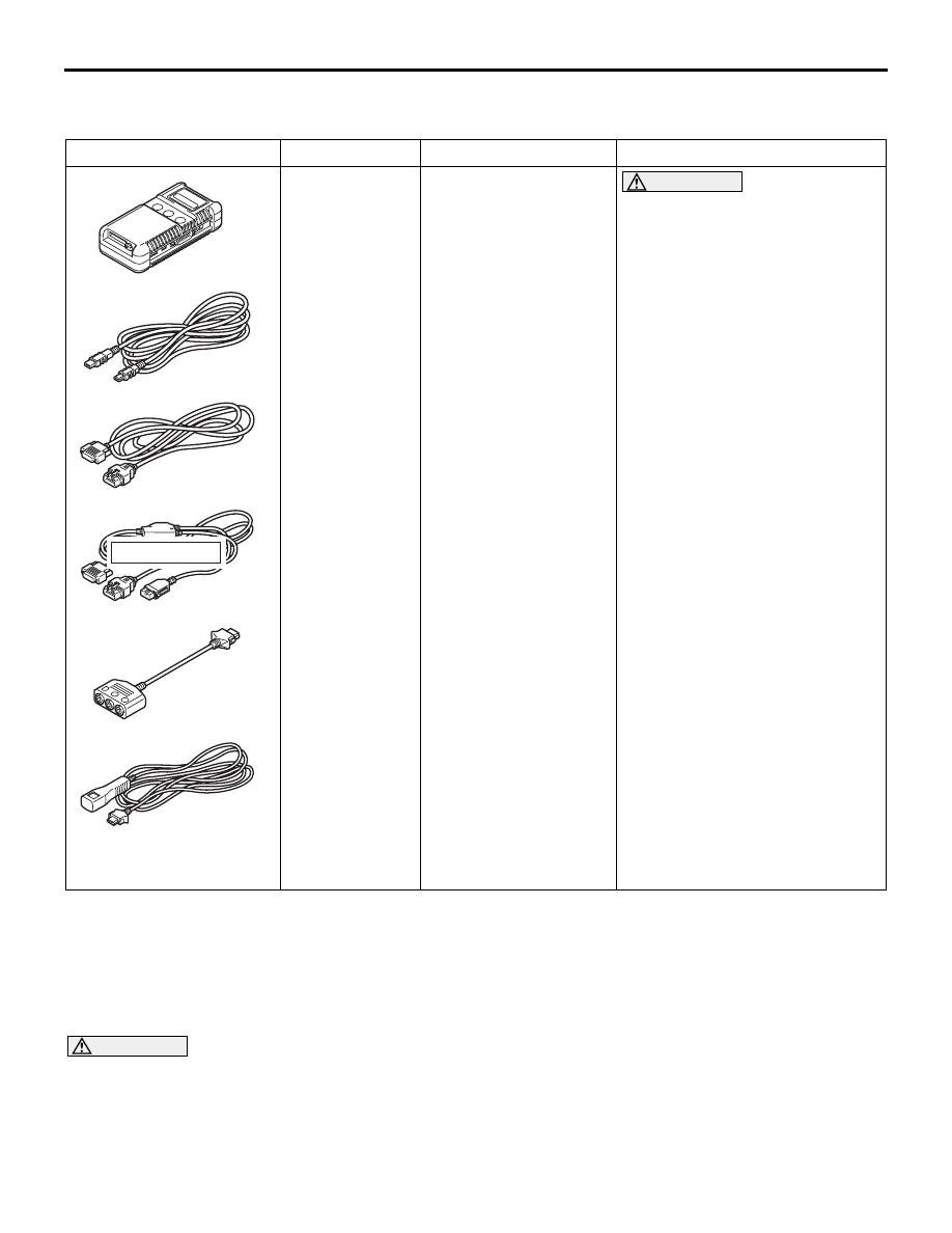
DO NOT USE
MB991955
A: MB991824
B: MB991827
C: MB991910
D: MB991911
E: MB991825
F: MB991826
M.U.T.-III sub assembly
A: Vehicle
communication
interface (V.C.I.)
B: M.U.T.-III USB cable
C: M.U.T.-III main
harness A (Vehicles
with CAN
communication
system)
D: M.U.T.-III main
harness B (Vehicles
without CAN
communication
system)
E: M.U.T.-III adapter
harness
F: M.U.T.-III trigger
harness
For vehicles with CAN
communication, use M.U.T.-III
main harness A to send
simulated vehicle speed. If you
connect M.U.T.-III main harness
B instead, the CAN
communication does not
function correctly.
Measurement of turbocharger
supercharging pressure
ON-VEHICLE SERVICE
TURBOCHARGER SUPERCHARGING
PRESSURE CHECK
M1151001001069
CAUTION
Conduct the driving test in a location where driv-
ing at full acceleration can be done with safety.
Two person should be in the vehicle when the
test is conducted; the person in the passenger
seat should read the indications shown by the
M.U.T.-III.
1. Set the vehicle to the pre-inspection condition.
CAUTION