Mitsubishi L200. Manual - part 174


  Index      Mitsubishi     Mitsubishi L200 - service repair manual 2012 year


Search            


Content   ..  172  173  174  175   ..


Mitsubishi L200. Manual - part 174


TROUBLESHOOTING

DIESEL FUEL

13A-492

YES : 

Replace the engine-ECU. When the engine-

ECU is replaced, write the chassis number 
(Refer to GROUP 00 

− Precautions Before 

Service 

− How to Perform Chassis Number 

Writing ). After replacing the engine-ECU, 
register the injector identification code and 
learn fuel injection (Refer to GROUP 00 

− 

Precautions Before Service 

− What The 

Common Rail Engine Learns ). After 
registering the injector identification code, 
the vehicle equipped with the DPF carries 
out the forcible DPF regeneration. (Refer to 
GROUP 17 

− Emission Control − Diesel 

Particulate Filter (DPF) System 

− Forcible 

DPF Regeneration ).

NO : 

Intermittent malfunction (Refer to GROUP 
00 

− How to Use Troubleshooting/

Inspection Service Points 

− How to Cope 

with Intermittent Malfunction ).

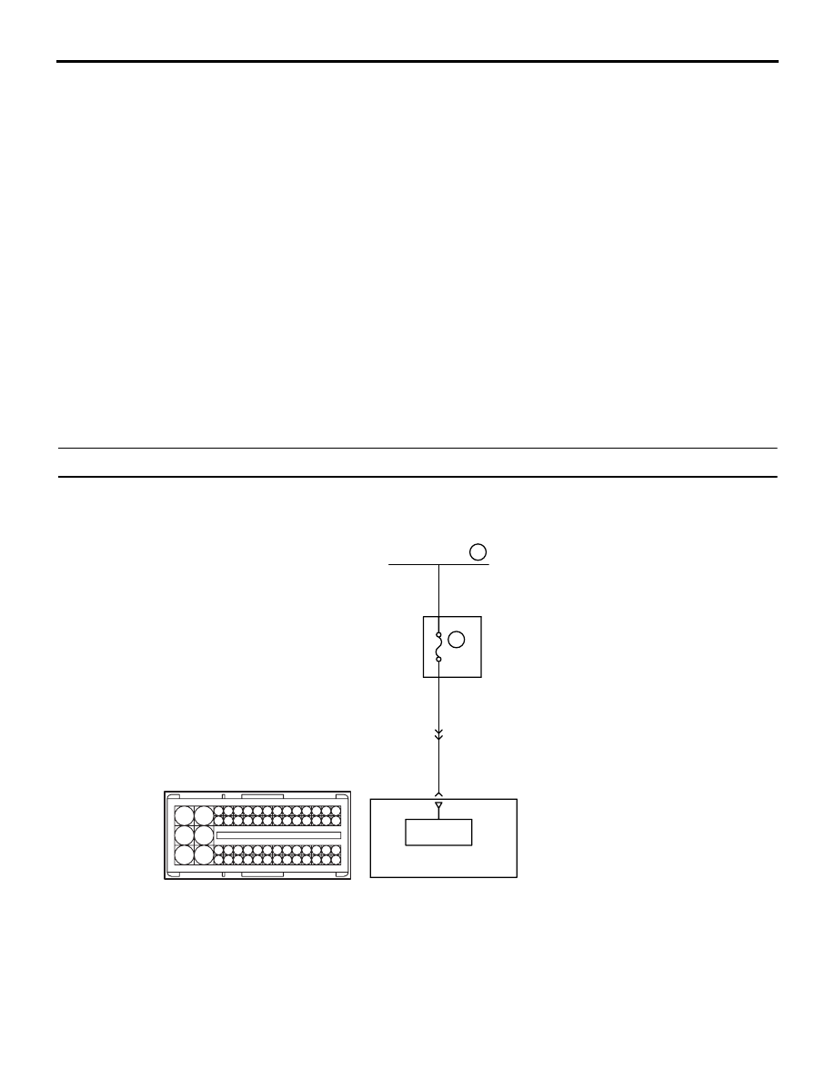
Inspection Procedure 17: Engine-ECU Battery Back-up System

OPERATION

• Backup power source is directly supplied to an 

engine-ECU from a battery.

AKA00116

101 102

103104 105 106107 108109 110 111112 113 114115

118119 120 121122 123124 125126127 128 129130

131132 133 134135 136137 138139140 141142 143

146147 148 149150 151152 153154155 156 157158

117

145

116

144

C-103

10

20A

Fusible link

103

Battery
backup

3

A-115

Relay 
box

W-R

W-B

W-B

Battery back-up circuit

Wire colour code
B: Black  LG: Light green  G: Green  L: Blue  W: White  Y: Yellow  SB: Sky blue  BR: Brown  O: Orange  GR: Grey
R: Red  P: Pink  V: Violet  PU: Purple  SI: Silver

Engine-ECU

23

AB

TROUBLESHOOTING

DIESEL FUEL

13A-493

PROBABLE CAUSES

• Damaged harness (Open circuit between engine-

ECU and relay box)

• Damaged connector (Engine-ECU connector)

• Failed engine-ECU

DIAGNOSIS PROCEDURE

STEP 1. Check battery voltage.

• Measure battery voltage during cranking.

OK: 8 V or more

Q: Is the check result normal?

YES : 

Go to Step 2 .

NO : 

Check battery (Refer to GROUP 54A 

− 

Battery 

− On-vehicle Service − Battery test 

).

STEP 2. Perform voltage measurement at C-103 
engine-ECU connector.

• Disconnect connector, and measure at harness 

side.

• Voltage between terminal No. 103 and earth.

OK: System voltage

Q: Is the check result normal?

YES : 

Go to Step 5 .

NO : 

Go to Step 3 .

STEP 3. Connector check: C-103 engine-ECU 
connector and A-115 intermediate connector.

Q: Are the check results normal?

YES : 

Go to Step 4 .

NO : 

Repair or replace.

AKA00090

101

102

103

104

105

106

107

108

109

110

111

112

113

114

115

118

119

120

121

122

123

124

125

126

127

128

129

130

131

132

133

134

135

136

137

138

139

140

141

142

143

146

147

148

149

150

151

152

153

154

155

156

157

158

117

145

116

144

C-103 (B)

C-103 (B)

<R.H. drive vehicles>

Harness side connector

<L.H. drive vehicles>

Connector: C-103

AB

AK700922

1 2

3

6 7 8

4

5

9 10

AB

A-115

Harness side connector

A-115

Connector: A-115

<L.H. drive vehicles>

<R.H. drive vehicles>

TROUBLESHOOTING

DIESEL FUEL

13A-494

STEP 4. Check for open circuit between C-103 
(terminal No. 103) engine-ECU connector and A-
115 (terminal No. 3) intermediate connector.

• Disconnect connector.

Q: Is the check result normal?

YES : 

Go to Step 5 .

NO : 

Repair the harness wire.

STEP 5. Check the trouble symptoms.

Q: Does trouble symptom persist?

YES : 

Replace the engine-ECU. When the engine-

ECU is replaced, write the chassis number 
(Refer to GROUP 00 

− Precautions Before 

Service 

− How to Perform Chassis Number 

Writing ). After replacing the engine-ECU, 
register the injector identification code and 
learn fuel injection (Refer to GROUP 00 

− 

Precautions Before Service 

− What The 

Common Rail Engine Learns ). After 
registering the injector identification code, 
the vehicle equipped with the DPF carries 
out the forcible DPF regeneration. (Refer to 
GROUP 17 

− Emission Control − Diesel 

Particulate Filter (DPF) System 

− Forcible 

DPF Regeneration ).

NO : 

Intermittent malfunction (Refer to GROUP 
00 

− How to Use Troubleshooting/

Inspection Service Points 

− How to Cope 

with Intermittent Malfunction ).

AKA00090

101

102

103

104

105

106

107

108

109

110

111

112

113

114

115

118

119

120

121

122

123

124

125

126

127

128

129

130

131

132

133

134

135

136

137

138

139

140

141

142

143

146

147

148

149

150

151

152

153

154

155

156

157

158

117

145

116

144

C-103 (B)

C-103 (B)

<R.H. drive vehicles>

Harness side connector

<L.H. drive vehicles>

Connector: C-103

AB

AK700922

1 2

3

6 7 8

4

5

9 10

AB

A-115

Harness side connector

A-115

Connector: A-115

<L.H. drive vehicles>

<R.H. drive vehicles>

TROUBLESHOOTING

DIESEL FUEL

13A-495

Inspection Procedure 18: 1st and 2nd Rail Switch System <M/T>

OPERATION

• The 1st and 2nd rail switches detect that a trans-

mission is shifted into the 1st speed gear posi-
tion.

• An engine-ECU controls an engine speed to be 3, 

000 r/min or less so that an excessive load can-
not be applied to a drive train system due to a 
sudden start in the first gear position.

PROBABLE CAUSES

• Failed 1st and 2nd rail switch

AKB00289

1

2

3

4

5 6 7 8 9

10 1112 13 14 15 16 17 18 19 20 21 22 23 24

25 26

27 28 29 30 31 32 33 34 35 36 37 38 39 40 41 42

49 50 51 52 53 54 55 56 57 58 59 60 61 62 63 64 65 66 67 68 69 70 71 72

43 44 45 46 47 48

73 74 75 76 77 78 79 80 81 82 83 84 85 86 87 88 89 90 91 92 93 94 95 96

2

1

Ignition switch (IG1)

11

L-B

L-Y

L-Y

G-Y

G-Y

G-Y

1st and 2nd Rail Switch Circuit

Wire colour code
B: Black  LG: Light green  G: Green  L: Blue  W: White  Y: Yellow  SB: Sky blue  BR: Brown  O: Orange  GR: Grey
R: Red  P: Pink  V: Violet  PU: Purple  SI: Silver

Engine-ECU

1st and 2nd rail switch

21

7.5A

2

J/B

C-208

C-207

4

C-30

10

1

C-29

2

4

A-115

6

OFF

ON

C-105

B-06

MU802662

AC


Content   ..  172  173  174  175   ..