Mitsubishi L200. Manual - part 162


  Index      Mitsubishi     Mitsubishi L200 - service repair manual 2012 year


Search            


Content   ..  160  161  162  163   ..


Mitsubishi L200. Manual - part 162


TROUBLESHOOTING

DIESEL FUEL

13A-444

Inspection Procedure 4: Starting Impossible (No Initial Combustion) <M/T>

1

2

3
4

1

1

AKB00285

101 102

103104 105 106107 108109 110 111112 113 114115

118119 120 121122 123124 125126127 128 129130

131132 133 134135 136137 138139140 141142 143

146147 148 149150 151152 153154155 156 157158

117

145

116

144

1 2 3
4 5 6

Wire colour code
B: Black  LG: Light green  G: Green  L: Blue  W: White  Y: Yellow  SB: Sky blue  BR: Brown  O: Orange  GR: Grey
R: Red  P: Pink  V: Violet  PU: Purple  SI: Silver

IG2

ST

LOCK

ACC

IG1

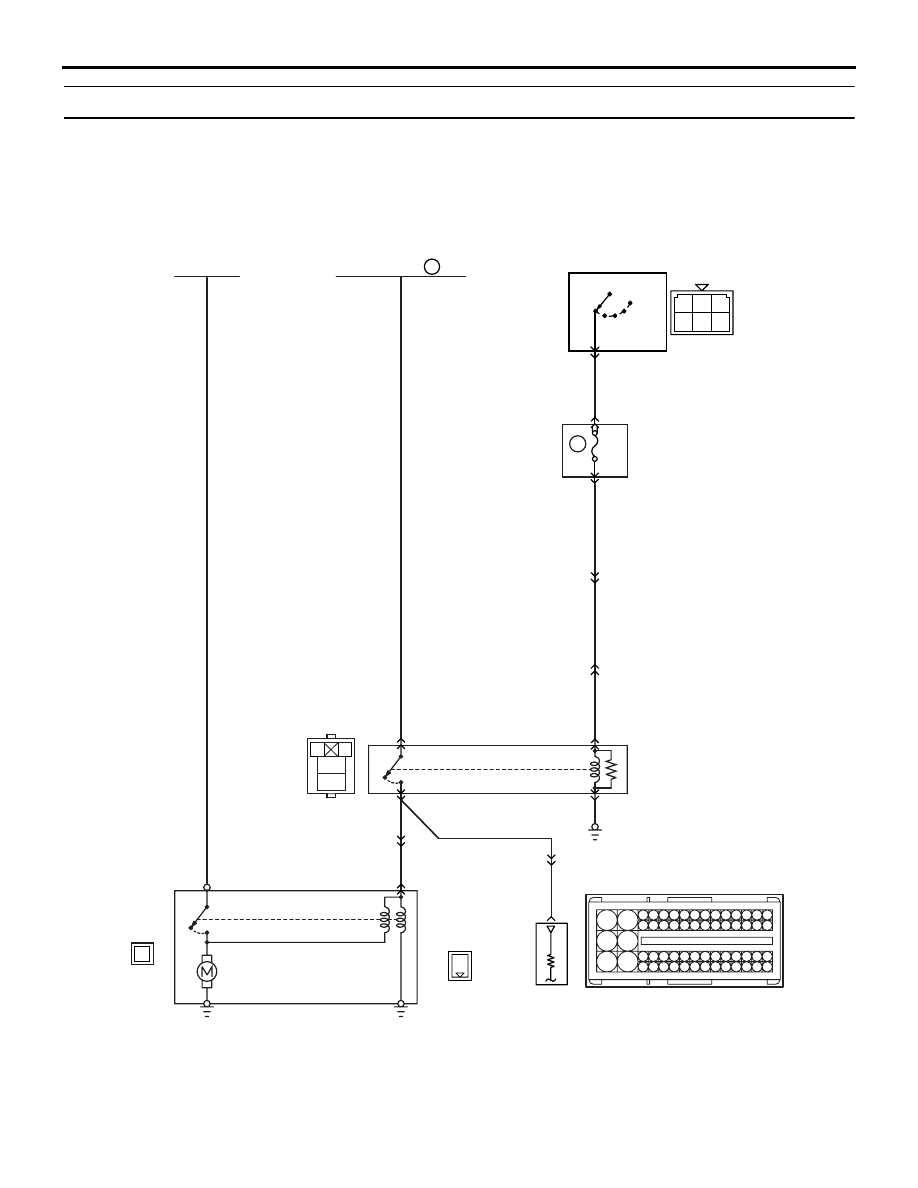
Starting Impossible (no initial combustion) <M/T>

Battery

Fusible link

Ignition switch

3

5

5

11

2

4

1

B

3

ON

OFF

ON

OFF

1

1

6

J/B

2

4

7.5A

C-211

C-207

10

A-115

8

A-115

A-27

A-115

R-B

R-B

B-R

W

B-L

B-L

G-R

A-16X

A-10

A-110

(MU801211)

C-103

B-W

Y

B-Y

Engine-ECU

Starter
relay

Starter

C-307

111

AB

TROUBLESHOOTING

DIESEL FUEL

13A-445

COMMENT ON TROUBLE SYMPTOM

• Failure is possibly caused by failed starter itself 

or failed related circuit.

PROBABLE CAUSES

• Failed battery

• Failed starter motor

• Failed starter relay

• Open/short circuit in starter associated circuit or 

loose connector contact

• Failed engine-ECU

DIAGNOSIS PROCEDURE

STEP 1. Check battery voltage.

• Measure battery voltage at cranking.

OK: 8 V or higher

Q: Is the check result normal?

YES : 

Go to Step 2.

NO : 

Check battery (Refer to GROUP 54A 

− 

Battery 

− On-vehicle Service − Battery Test 

).

STEP 2. M.U.T.-III data list

• Item 40: Starter switch

OK: 

ON (Ignition switch: ST)
OFF (Ignition switch: ON)

Q: Is the check result normal?

YES : 

Go to Step 13.

NO : 

Go to Step 3.

STEP 3. Connector check: A-16X starter relay 
connector

Q: Is the check result normal?

YES : 

Go to Step 4.

NO : 

Repair or replace.

STEP 4. Check starter relay.

• Check starter relay (Refer to GROUP 16 − Start-

ing System 

− Starter Relay Check )

Q: Is the check result normal?

YES : 

Go to Step 5.

NO : 

Replace the starter relay.

STEP 5. Perform voltage measurement at A-16X 
starter relay connector.

• Disconnect connector, and measure at the har-

ness side.

• Ignition switch: ST

• Voltage between terminal No. 2 and earth.

OK: System voltage

Q: Is the check result normal?

YES : 

Go to Step 8.

NO : 

Go to Step 6.

AK501014

2

1

3
4

AC

A-16X

Connector: A-16X

Relay box's side connector

AK501014

2

1

3
4

AC

A-16X

Connector: A-16X

Relay box's side connector

TROUBLESHOOTING

DIESEL FUEL

13A-446

STEP 6. Connector check: C-307 ignition switch 
connector

Q: Is the check result normal?

YES : 

Go to Step 7.

NO : 

Repair or replace.

STEP 7. Check ignition switch.

• Check ignition switch (Refer to GROUP 54A − 

Ignition Switch 

− Inspection ).

Q: Is the check result normal?

YES : 

Check intermediate connectors A-115, C-

207 and C-211, and repair if necessary. If 
intermediate connectors are normal, check 
and repair harness between A-16X (terminal 
No. 2) starter relay connector and C-307 
(terminal No. 5) ignition switch connector.

• Check power supply line for open/

short circuit.

NO : 

Replace the ignition switch.

AKB00286

1

2

3

4

5

6

C-307

Connector: C-307

<R.H. drive vehicles>

C-307

AB

Harness side connector

<L.H. drive vehicles>

AK501014

2

1

3
4

AC

A-16X

Connector: A-16X

Relay box's side connector

AKB00286

1

2

3

4

5

6

C-307

Connector: C-307

<R.H. drive vehicles>

C-307

AB

Harness side connector

<L.H. drive vehicles>

TROUBLESHOOTING

DIESEL FUEL

13A-447

STEP 8. Perform voltage measurement at A-16X 
starter relay connector. 

• Disconnect connector, and measure at the har-

ness side.

• Voltage between terminal No. 4 and earth.

OK: System voltage

Q: Is the check result normal?

YES : 

Go to Step 9.

NO : 

Check and repair harness between A16X 

(terminal No. 4) starter relay connector and 
battery.

• Check power supply line for open/

short circuit.

STEP 9. Perform resistance measurement at A-
16X starter relay connector.

• Disconnect connector, and measure at harness 

side.

• Resistance between terminal No. 1 and earth.

OK: Continuity (2

 or less)

Q: Is the check result normal?

YES : 

Go to Step 10.

NO : 

Check and repair harness between A16X 

(terminal No. 1) starter relay connector and 
body earth.

• Check earth line for open circuit and 

damage.

STEP 10. Connector check: A-110 starter 
connector 

Q: Is the check result normal?

YES : 

Go to Step 11.

NO : 

Repair or replace.

STEP 11. Check harness between A-110 (terminal 
No. 1) starter connector and A-16X (terminal No. 
3) starter relay connector.

NOTE: Before checking harness, check intermediate 
connector A-27, and repair if necessary.

• Check output line for open/short circuit.

Q: Is the check result normal?

YES : 

Go to Step 12.

NO : 

Repair the damaged harness wire.

AK501014

2

1

3
4

AC

A-16X

Connector: A-16X

Relay box's side connector

AK501014

2

1

3
4

AC

A-16X

Connector: A-16X

Relay box's side connector

AK700920

1

Harness side connector

Connector: A-110

AB

A-110 (B)

AK700920

1

Harness side connector

Connector: A-110

AB

A-110 (B)

AK501014

2

1

3
4

AC

A-16X

Connector: A-16X

Relay box's side connector


Content   ..  160  161  162  163   ..