Mitsubishi L200. Manual - part 161


  Index      Mitsubishi     Mitsubishi L200 - service repair manual 2012 year


Search            


Content   ..  159  160  161  162   ..


Mitsubishi L200. Manual - part 161


TROUBLESHOOTING

DIESEL FUEL

13A-440

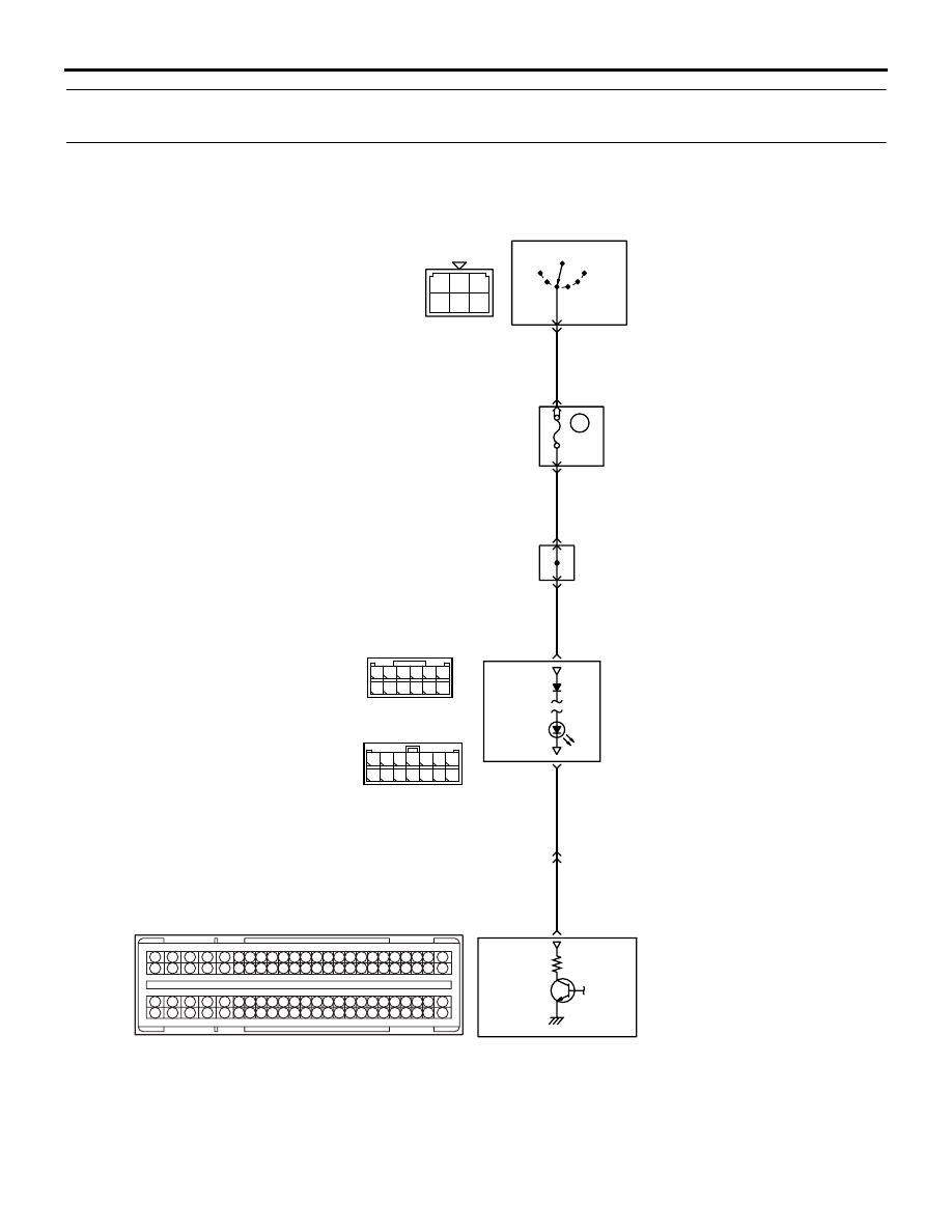
Inspection Procedure 3: The Engine Warning Lamp Remains Illuminating and Never Goes Out or Is 
Blinking.

AKB00284

60

58

61 62 63 64

59

51

55

54

53

56 57

52

39

37

40 41 42

38

31

35

34

33

36

32

1

2

3

4

5 6 7 8 9

10 1112 13 14 15 16 17 18 19 20 21 22 23 24

25 26

27 28 29 30 31 32 33 34 35 36 37 38 39 40 41 42

49 50 51 52 53 54 55 56 57 58 59 60 61 62 63 64 65 66 67 68 69 70 71 72

43 44 45 46 47 48

73 74 75 76 77 78 79 80 81 82 83 84 85 86 87 88 89 90 91 92 93 94 95 96

1 2 3
4 5 6

15

7.5A

C-207

C-209

C-112

B-W

B-W

Engine
warning
lamp

Combination meter

4

6

12

15

J/B

C-112

C-111

MU801586

36

Wire colour code
B: Black  LG: Light green  G: Green  L: Blue  W: White  Y: Yellow  SB: Sky blue  BR: Brown  O: Orange  GR: Grey
R: Red  P: Pink  V: Violet  PU: Purple  SI: Silver

L-B

2

R

IG2

ST

LOCK

ACC

IG1

Ignition switch

C-307

R-W

R-W

Engine-ECU

C-53*¹ or
C-35*²

C-105

C-111

63

46

23

J/C (5)

C-132

Engine Warning Lamp (check engine lamp) Circuit

NOTE

*1: L.H. drive vehicles
*2: R.H. drive vehicles

AB

TROUBLESHOOTING

DIESEL FUEL

13A-441

OPERATION

• Engine-ECU has detected failed sensor or failed 

actuator. Or failure is possibly caused by short 
circuit or other faults.

PROBABLE CAUSES

• Damaged connector (Engine-ECU connector, 

combination meter connector)

• Damaged harness (Short circuit between engine-

ECU and combination meter)

• Failed combination meter

• Failed engine-ECU

DIAGNOSIS PROCEDURE

STEP 1. Check the illuminating condition of the 
engine warning lamp.

Q: Is the engine warning lamp blinking?

YES : 

Carry out the small injection quantity 

learning procedure (Refer to GROUP 00 

− 

Precautions Before Service 

− Small 

Injection Quantity Learning Procedure ).

NO : 

Go to Step 2 .

STEP 2. M.U.T.-III diagnosis code.

Q: Is the diagnosis code set?

YES : 

Inspection chart for diagnosis code (Refer 

to 

P.13A-21

).

NO : 

Go to Step 3 .

STEP 3. Connector check: C-105 engine-ECU 
connector and C-111 combination meter 
connector

Q: Are the check results normal?

YES : 

Go to Step 4 .

NO : 

Repair or replace.

AKA00089

1

2

3

4

5

6

7

8

9

10

11

12

13

14

15

16

17

18

19

20

21

22

23

24

25

26

27

28

29

30

31

32

33

34

35

36

37

38

39

40

41

42

49

50

51

52

53

54

55

56

57

58

59

60

61

62

63

64

65

66

67

68

69

70

71

72

43

44

45

46

47

48

73

74

75

76

77

78

79

80

81

82

83

84

85

86

87

88

89

90

91

92

93

94

95

96

C-105 (B)

C-105 (B)

<R.H. drive vehicles>

Harness side connector

<L.H. drive vehicles>

Connector: C-105

AB

AK700806

62

64

61 60 59 58

63

57

53

54

55

52 51

56

Harness side connector 

C-111

C-111

Connector: C-111

<R.H. drive vehicles>

<L.H. drive vehicles>

AB

TROUBLESHOOTING

DIESEL FUEL

13A-442

STEP 4. Check combination meter.

• Ignition switch: ON

• Disconnect C-111 combination meter connector

Q: Does the engine warning lamp go out?

YES : 

Go to Step 5 .

NO : 

Check combination meter (Refer to GROUP 
54A 

− Combination Meter − Check Chart for 

Trouble Symptoms ).

AK700806

62

64

61 60 59 58

63

57

53

54

55

52 51

56

Harness side connector 

C-111

C-111

Connector: C-111

<R.H. drive vehicles>

<L.H. drive vehicles>

AB

TROUBLESHOOTING

DIESEL FUEL

13A-443

STEP 5. Perform resistance measurement for 
short circuit at C-105 engine-ECU connector. 

• Disconnect connector, and measure at harness 

side.

• Disconnect C-111 combination meter connector.

• Voltage between terminal No. 46 and earth.

OK: 1 k

 or more

Q: Is the check result normal?

YES : 

Go to Step 6 .

NO : 

Repair the harness wire.

STEP 6. Check injector identification code.

• Check injector identification code (Refer to 

GROUP 00 

− Precautions Before Service − Injec-

tor Identification code Registration Procedure ).

Q: Is the check result normal?

YES : 

Go to Step 7 .

NO : 

Register the injector ID.

STEP 7. Small injection quantity learning.

• Carry out the small injection quantity learning 

procedure (Refer to GROUP 00 

− Precautions 

Before Service 

− Small Injection Quantity Learn-

ing Procedure ).

Q: Does trouble symptom persist?

YES : 

Replace the engine-ECU. When the engine-

ECU is replaced, write the chassis number 
(Refer to GROUP 00 

− Precautions Before 

Service 

− How to Perform Chassis Number 

Writing ). After replacing the engine-ECU, 
register the injector identification code and 
learn fuel injection (Refer to GROUP 00 

− 

Precautions Before Service 

− What The 

Common Rail Engine Learns ). After 
registering the injector identification code, 
the vehicle equipped with the DPF carries 
out the forcible DPF regeneration. (Refer to 
GROUP 17 

− Emission Control − Diesel 

Particulate Filter (DPF) System 

− Forcible 

DPF Regeneration ).

NO : 

The procedure is complete.

AKA00089

1

2

3

4

5

6

7

8

9

10

11

12

13

14

15

16

17

18

19

20

21

22

23

24

25

26

27

28

29

30

31

32

33

34

35

36

37

38

39

40

41

42

49

50

51

52

53

54

55

56

57

58

59

60

61

62

63

64

65

66

67

68

69

70

71

72

43

44

45

46

47

48

73

74

75

76

77

78

79

80

81

82

83

84

85

86

87

88

89

90

91

92

93

94

95

96

C-105 (B)

C-105 (B)

<R.H. drive vehicles>

Harness side connector

<L.H. drive vehicles>

Connector: C-105

AB

AK700806

62

64

61 60 59 58

63

57

53

54

55

52 51

56

Harness side connector 

C-111

C-111

Connector: C-111

<R.H. drive vehicles>

<L.H. drive vehicles>

AB


Content   ..  159  160  161  162   ..