Mitsubishi L200. Manual - part 155


  Index      Mitsubishi     Mitsubishi L200 - service repair manual 2012 year


Search            


Content   ..  153  154  155  156   ..


Mitsubishi L200. Manual - part 155


TROUBLESHOOTING

DIESEL FUEL

13A-416

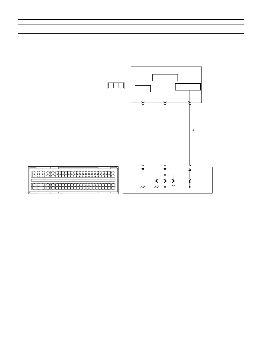
Code No. P2455: Exhaust Differential Pressure Sensor Circuit High Input <Euro5>

OPERATION

• A power voltage of 5 V is applied to the exhaust 

differential pressure sensor power terminal (ter-
minal No. 3) from the engine-ECU (terminal No. 
94) and earthed to the engine-ECU (terminal No. 
80) from the exhaust differential pressure sensor 
(terminal No. 2).

• The sensor signal is inputted to the engine-ECU 

(terminal No. 56) from the exhaust differential 
pressure sensor output terminal (terminal No. 1).

FUNCTION

• The exhaust differential pressure sensor outputs 

the voltage to the engine-ECU in accordance with 
the difference in the voltage between the DPF 
upstream area and the DPF down stream area.

• The engine-ECU anticipates the amount of PM 

accumulated in the DPF through this output volt-
age.

TROUBLE JUDGMENT

Check Conditions

• Battery positive voltage is 8 − 16 V

• 2 seconds later after the ignition switch has been 

in "ON" position or the engine has started up

Judgment Criterion

• The exhaust differential pressure sensor output 

voltage is 4.79 V or more.

PROBABLE CAUSES

• Failed exhaust differential pressure sensor

• Open circuit in exhaust differential pressure sen-

sor circuit or loose connector contact

• Failed engine-ECU

AKB00280

1

2

3

4

5 6 7 8 9

10 1112 13 14 15 16 17 18 19 20 21 22 23 24

25 26

27 28 29 30 31 32 33 34 35 36 37 38 39 40 41 42

49 50 51 52 53 54 55 56 57 58 59 60 61 62 63 64 65 66 67 68 69 70 71 72

43 44 45 46 47 48

73 74 75 76 77 78 79 80 81 82 83 84 85 86 87 88 89 90 91 92 93 94 95 96

1 2 3

AB

80

GR-B

P-G

B-O

56

94

A-148

Exhaust differential
pressure sensor 

2

1

3

Exhaust Differential Pressure Sensor Circuit

C-105

5 V

Earth

Output signal

Power source

Wire colour code
B: Black  LG: Light green  G: Green  L: Blue  W: White  Y: Yellow  SB: Sky blue  BR: Brown  O: Orange  GR: Grey
R: Red  P: Pink  V: Violet  PU: Purple  SI: Silver

TROUBLESHOOTING

DIESEL FUEL

13A-417

DIAGNOSTIC PROCEDURE

STEP 1. M.U.T.-III data list

• Refer to Data List Reference Table 

P.13A-542

.

a. Item 120: exhaust differential pressure sensor

Q: Is the check result normal?

YES : 

Intermittent malfunction (Refer to GROUP 

00 

− How to Use Troubleshooting/

Inspection Service Points 

− How to Cope 

with Intermittent Malfunctions ).

NO : 

Go to Step 2 .

STEP 2. Connector check: A-148 exhaust 
differential pressure sensor connector

Q: Is the check result normal?

YES : 

Go to Step 3 .

NO : 

Repair or replace the connector.

STEP 3. Perform resistance measurement at A-
148 exhaust differential pressure sensor 
connector.

• Disconnect connector, and measure at harness 

side.

• Ignition switch: ON

• Resistance between terminal No. 2 and earth.

OK: Continuity (2 

 or less)

Q: Is the check result normal?

YES : 

Go to Step 7 . 

NO : 

Go to Step 4 

STEP 4. Connector check: C-105 engine-ECU 
connector

Q: Is the check result normal?

YES : 

Go to Step 5 .

NO : 

Repair or replace the connector.

AKB00281

3 2 1

AB

A-148 (B)

Harness side
connector

Connector: A-148

AKB00281

3 2 1

AB

A-148 (B)

Harness side
connector

Connector: A-148

AKA00089

1

2

3

4

5

6

7

8

9

10

11

12

13

14

15

16

17

18

19

20

21

22

23

24

25

26

27

28

29

30

31

32

33

34

35

36

37

38

39

40

41

42

49

50

51

52

53

54

55

56

57

58

59

60

61

62

63

64

65

66

67

68

69

70

71

72

43

44

45

46

47

48

73

74

75

76

77

78

79

80

81

82

83

84

85

86

87

88

89

90

91

92

93

94

95

96

C-105 (B)

C-105 (B)

<R.H. drive vehicles>

Harness side connector

<L.H. drive vehicles>

Connector: C-105

AB

TROUBLESHOOTING

DIESEL FUEL

13A-418

STEP 5. Check harness between A-148 (terminal 
No. 2) exhaust differential pressure sensor 
connector and C-105 (terminal No. 80) engine-
ECU connector.

• Check earthing line for open circuit and damage.

Q: Is the check result normal?

YES : 

Go to Step 6 .

NO : 

Repair the damaged harness wire.

STEP 6. M.U.T.-III data list

• Refer to Data List Reference Table 

P.13A-542

.

a. Item 120: exhaust differential pressure sensor

Q: Is the check result normal?

YES : 

Intermittent malfunction (Refer to GROUP 

00 

− How to Use Troubleshooting/

Inspection Service Points 

− How to Cope 

with Intermittent Malfunctions ). 

NO : 

Replace the engine-ECU. When the engine-
ECU is replaced, write the chassis number 
(Refer to GROUP 00 

− Precautions Before 

Service 

− How to Perform Chassis Number 

Writing ). After replacing the engine-ECU, 
register the injector identification code and 
learn fuel injection (Refer to GROUP 00 

− 

Precautions Before Service 

− What The 

Common Rail Engine Learns ). After 
registering the injector identification code, 
carry out the forcible DPF regeneration. 
(Refer to GROUP 17 

− Emission Control − 

Diesel Particulate Filter (DPF) System 

− 

Forcible DPF Regeneration ).

STEP 7. Replace the exhaust differential 
pressure sensor

• After replacing the exhaust differential pressure 

sensor, Carry out the forcible DPF regeneration. 
(Refer to GROUP 17 

− Emission Control − Diesel 

Particulate Filter (DPF) System 

− Forcible DPF 

Regeneration ). After carrying out the forcible 
DPF regeneration, re-check the trouble symp-
toms.

Q: Is the check result normal?

YES : 

Go to Step 6 .

NO : 

Check end.

Code No. P252F: Engine Oil Level Malfunction <Euro5>

FUNCTION

• The engine oil level may ascend if the fuel runs 

into the engine oil on the DPF regeneration.

• The engine-ECU monitors the engine driving con-

ditions to estimate the ascend of engine oil level.

TROUBLE JUDGMENT

Check Condition

• Ignition switch is in "ON" position.

Judgement Criterion

• The estimated increased amount of the engine oil 

exceeds the 1,000 cc.

PROBABLE CAUSE

• The engine oil is increased.

AKB00281

3 2 1

AB

A-148 (B)

Harness side
connector

Connector: A-148

AKA00089

1

2

3

4

5

6

7

8

9

10

11

12

13

14

15

16

17

18

19

20

21

22

23

24

25

26

27

28

29

30

31

32

33

34

35

36

37

38

39

40

41

42

49

50

51

52

53

54

55

56

57

58

59

60

61

62

63

64

65

66

67

68

69

70

71

72

43

44

45

46

47

48

73

74

75

76

77

78

79

80

81

82

83

84

85

86

87

88

89

90

91

92

93

94

95

96

C-105 (B)

C-105 (B)

<R.H. drive vehicles>

Harness side connector

<L.H. drive vehicles>

Connector: C-105

AB

TROUBLESHOOTING

DIESEL FUEL

13A-419

DIAGNOSIS PROCEDURE

STEP 1. Replace the engine oil.

• Replace the engine oil, When the engine oil is 

replaced, initialise the learning value (Refer to 
GROUP 00 

− Precautions before Service − Initial-

isation Procedure for Learning Value in Diesel 
Particulate Filter (DPF) System ). After initialising 
the learning value, reconfirm diagnosis code.

Q: Is the diagnosis code set?

YES : 

Replace the engine-ECU. When the engine-

ECU is replaced, write the chassis number 
(Refer to GROUP 00 

− Precautions Before 

Service 

− How to Perform Chassis Number 

Writing ). After replacing the engine-ECU, 
register the injector identification code and 
learn fuel injection (Refer to GROUP 00 

− 

Precautions Before Service 

− What The 

Common Rail Engine Learns ). After 
registering the injector identification code, 
carry out the forcible DPF regeneration. 
(Refer to GROUP 17 

− Emission Control − 

Diesel Particulate Filter (DPF) System 

− 

Forcible DPF Regeneration ).

NO : 

Check end.

Code No. U1073: Bus Off

CAUTION

If diagnosis code U1073 is output from engine-
ECU surely perform CAN busline diagnosis.

CAUTION

Replace ECU after certainly confirming that the 
communication circuits are normal.
TROUBLE JUDGMENT

Check Condition

• All the time

Judgment Criterion

• When the buss off error is detected.

COMMENT ON TROUBLE SYMPTOM

• The failure is possibly caused by malfunction of 

the harness and connector in CAN busline or by 
malfunction in engine-ECU.

PROBABLE CAUSE

• Failed engine-ECU

DIAGNOSIS PROCEDURE

STEP 1. M.U.T.-III CAN bus diagnostics

• Using M.U.T.-III, perform CAN busline diagnosis.

Q: Is the check result normal?

YES : 

 Go to Step 2 .

NO : 

Correct CAN busline (Refer to GROUP 54C 
− Troubleshooting − Can Bus Diagnostics 
Table ), and then go to Step 3 .

STEP 2. M.U.T.-III diagnosis code

• Reconfirm whether the diagnosis codes are out-

put from engine-ECU.

1. Erase the diagnosis codes being output.
2. Ignition switch: "LOCK" (OFF) to ON
3. Confirm whether the diagnosis codes are output.

Q: Are the diagnosis codes output?

YES  : 

Replace the engine-ECU. When the 

engine-ECU is replaced, write the chassis 
number (Refer to GROUP 00 

− Precautions 

Before Service 

− How to Perform Chassis 

Number Writing ). After replacing the 
engine-ECU, register the injector 
identification code and learn fuel injection 
(Refer to GROUP 00 

− Precautions Before 

Service 

− What The Common Rail Engine 

Learns ). After registering the injector 
identification code, the vehicle equipped 
with the DPF carries out the forcible DPF 
regeneration. (Refer to GROUP 17 

− 

Emission Control 

− Diesel Particulate Filter 

(DPF) System 

− Forcible DPF Regeneration 

). and then go to Step 3 .

NO : 

Intermittent malfunction (Refer to GROUP 
00 

− How to Use Troubleshooting/

Inspection Service Points 

− How to Cope 

with Intermittent Malfunctions ).


Content   ..  153  154  155  156   ..