Mitsubishi L200. Manual - part 127


  Index      Mitsubishi     Mitsubishi L200 - service repair manual 2012 year


Search            


Content   ..  125  126  127  128   ..


Mitsubishi L200. Manual - part 127


TROUBLESHOOTING

DIESEL FUEL

13A-304

DIAGNOSIS PROCEDURE

STEP 1. Connector check: A-143 fuel filter 
pressure switch connector

Q: Is the check result normal?

YES : 

Go to Step 2 .

NO : 

Repair or replace the connector.

STEP 2. Check the fuel filter pressure switch 
itself.
Check the fuel filter pressure switch itself (Refer to 
GROUP 13B 

− Fuel Filter − Fuel Filter Inspection ).

Q: Is the check result normal?

YES : 

Replace the fuel filter body.

NO : 

Go to Step 3 .

STEP 3. Perform voltage measurement at A-143 
fuel filter pressure switch connector.

• Disconnect connector, and measure at harness 

side.

• Ignition switch: ON

• Voltage between terminal No. 1 and earth.

OK: System voltage

Q: Is the check result normal?

YES : 

Go to Step 7 .

NO : 

Go to Step 4 .

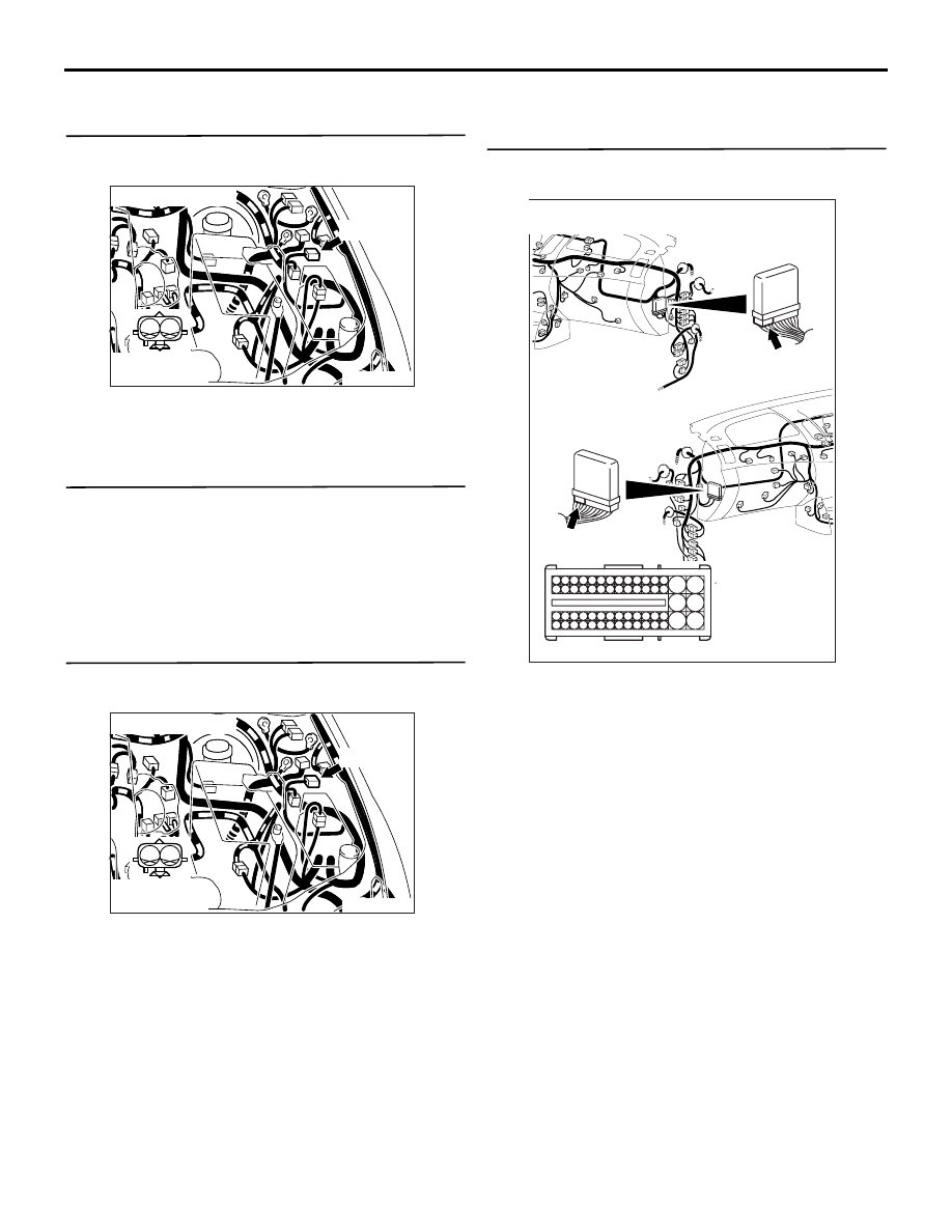
STEP 4. Connector check: C-103 engine-ECU 
connector

Q: Is the check result normal?

YES : 

Go to Step 5 .

NO : 

Repair or replace the connector.

AK700919

1

2

AC

Connector: A-143

A-143 (B)

Harness side
connector

AK700919

1

2

AC

Connector: A-143

A-143 (B)

Harness side
connector

AKA00090

101

102

103

104

105

106

107

108

109

110

111

112

113

114

115

118

119

120

121

122

123

124

125

126

127

128

129

130

131

132

133

134

135

136

137

138

139

140

141

142

143

146

147

148

149

150

151

152

153

154

155

156

157

158

117

145

116

144

C-103 (B)

C-103 (B)

<R.H. drive vehicles>

Harness side connector

<L.H. drive vehicles>

Connector: C-103

AB

TROUBLESHOOTING

DIESEL FUEL

13A-305

STEP 5. Check harness between A-143 (terminal 
No. 1) fuel filter pressure switch connector and 
C-103 (terminal No. 110) engine-ECU connector.

• Check output line for open/short circuit.

Q: Is the check result normal?

YES : 

Go to Step 6 .

NO : 

Repair the damaged harness wire.

STEP 6. M.U.T.-III data list

• Refer to Data List Reference Table 

P.13A-542

.

a. Item 152: Fuel filter pressure switch

Q: Is the check result normal?

YES : 

Intermittent malfunction (Refer to GROUP 

00 

− How to Use Troubleshooting/

Inspection Service Points 

− How to Cope 

with Intermittent Malfunctions ).

NO : 

Replace the engine-ECU. When the engine-
ECU is replaced, write the chassis number 
(Refer to GROUP 00 

− Precautions Before 

Service 

− How to Perform Chassis Number 

Writing ). After replacing the engine-ECU, 
register the injector identification code and 
learn fuel injection (Refer to GROUP 00 

− 

Precautions Before Service 

− What The 

Common Rail Engine Learns ).

STEP 7. Perform resistance measurement at A-
143 fuel filter pressure switch connector.

• Disconnect connector, and measure at harness 

side.

• Resistance between terminal No. 2 and earth.

OK: Continuity (2 

 or less)

Q: Is the check result normal?

YES : 

Go to Step 8 .

NO : 

Check and repair harness between A-143 

(terminal No. 2) fuel filter pressure switch 
connector and body earth.

• Check earthing line for open circuit 

and damage.

AK700919

1

2

AC

Connector: A-143

A-143 (B)

Harness side
connector

AKA00090

101

102

103

104

105

106

107

108

109

110

111

112

113

114

115

118

119

120

121

122

123

124

125

126

127

128

129

130

131

132

133

134

135

136

137

138

139

140

141

142

143

146

147

148

149

150

151

152

153

154

155

156

157

158

117

145

116

144

C-103 (B)

C-103 (B)

<R.H. drive vehicles>

Harness side connector

<L.H. drive vehicles>

Connector: C-103

AB

AK700919

1

2

AC

Connector: A-143

A-143 (B)

Harness side
connector

TROUBLESHOOTING

DIESEL FUEL

13A-306

STEP 8. Connector check: C-103 engine-ECU 
connector

Q: Is the check result normal?

YES : 

Go to Step 9 .

NO : 

Repair or replace the connector.

STEP 9. Check harness between A-143 (terminal 
No. 1) fuel filter pressure switch connector and 
C-103 (terminal No. 110) engine-ECU connector.

• Check output line for damage.

Q: Is the check result normal?

YES : 

Replace the fuel filter.

NO : 

Repair the damaged harness wire.

Code No. P1277: Fuel Filter Freeze <Vehicles with fuel filter pressure switch>

FUNCTION

• The engine-ECU estimates that the fuel filter is 

freezing, using the input signal from the each 
sensor.

• When storing this diagnosis code, the engine-

ECU blinks the glow lamp.

TROUBLE JUDGMENT

Check Conditions

• During steady driving

• Fuel temperature is lower than specified temper-

ature

• Engine coolant temperature is lower than speci-

fied temperature

AKA00090

101

102

103

104

105

106

107

108

109

110

111

112

113

114

115

118

119

120

121

122

123

124

125

126

127

128

129

130

131

132

133

134

135

136

137

138

139

140

141

142

143

146

147

148

149

150

151

152

153

154

155

156

157

158

117

145

116

144

C-103 (B)

C-103 (B)

<R.H. drive vehicles>

Harness side connector

<L.H. drive vehicles>

Connector: C-103

AB

AK700919

1

2

AC

Connector: A-143

A-143 (B)

Harness side
connector

AKA00090

101

102

103

104

105

106

107

108

109

110

111

112

113

114

115

118

119

120

121

122

123

124

125

126

127

128

129

130

131

132

133

134

135

136

137

138

139

140

141

142

143

146

147

148

149

150

151

152

153

154

155

156

157

158

117

145

116

144

C-103 (B)

C-103 (B)

<R.H. drive vehicles>

Harness side connector

<L.H. drive vehicles>

Connector: C-103

AB

TROUBLESHOOTING

DIESEL FUEL

13A-307

Judgment Criteria

• Determination of clogged fuel filter

• Fuel pressure hunting occurs more than certain 

degree, or difference more than certain degree 
exists between target fuel pressure and actual 
fuel pressure

PROBABLE CAUSE

• Fuel filter Freezing

DIAGNOSIS PROCEDURE

STEP 1. Reconfirmation of M.U.T.-III diagnosis 
code after warming up the engine

Q: Is any other diagnosis code than P1276 output?

YES : 

Inspection chart for diagnosis code (Refer 

to ).

NO : 

Check end.

Code No. P1298: Variable Geometry Turbocharger Control System Malfunction (high pressure) 
<Euro5>

FUNCTION

• The engine-ECU controls the duty ratio of the 

variable geometry control solenoid valve so that 
the actual boost pressure can become the target 
boost pressure.

TROUBLE JUDGMENT

Check Condition

• Engine is running

Judgment Criterion

• Actual boost pressure is higher than target boost 

pressure by more than 6.7 kPa

PROBABLE CAUSES

• Failed variable geometry turbocharger control 

system

• Failed engine-ECU

DIAGNOSTIC PROCEDURE

STEP 1. Check the turbocharger supercharging 
pressure.

• Check the turbocharger supercharging pressure 

(refer to GROUP 15 

− On-vehicle Service − Tur-

bocharger Supercharging Pressure Check ).

Q: Is the check result normal?

YES : 

Go to Step 2 .

NO : 

Repair the variable geometry turbocharger 
control system.

STEP 2. M.U.T.-III diagnosis code.

• After clearing the diagnosis code through M.U.T.-

III, start the engine and confirm whether the diag-
nosis code is output.

Q: Is the diagnosis code set?

YES : 

Replace the engine-ECU. When the engine-

ECU is replaced, write the chassis number 
(Refer to GROUP 00 

− Precautions Before 

Service 

− How to Perform Chassis Number 

Writing ). After replacing the engine-ECU, 
register the injector identification code and 
learn fuel injection (Refer to GROUP 00 

− 

Precautions Before Service 

− What The 

Common Rail Engine Learns ). After 
registering the injector identification code, 
carry out the forcible DPF regeneration. 
(Refer to GROUP 17 

− Emission Control − 

Diesel Particulate Filter (DPF) System 

− 

Forcible DPF Regeneration ).

NO : 

Intermittent malfunction (Refer to GROUP 
00 

− How to Use Troubleshooting/

Inspection Service Points 

− How to Cope 

with Intermittent Malfunctions ).

Code No. P1299: Variable Geometry Turbocharger Control System Malfunction (low pressure) 
<Euro5>

FUNCTION

• The engine-ECU controls the duty ratio of the 

variable geometry control solenoid valve so that 
the actual boost pressure can become the target 
boost pressure.

TROUBLE JUDGMENT

Check Condition

• Engine is running


Content   ..  125  126  127  128   ..