Mitsubishi L200. Manual - part 115


  Index      Mitsubishi     Mitsubishi L200 - service repair manual 2012 year


Search            


Content   ..  113  114  115  116   ..


Mitsubishi L200. Manual - part 115


TROUBLESHOOTING

DIESEL FUEL

13A-256

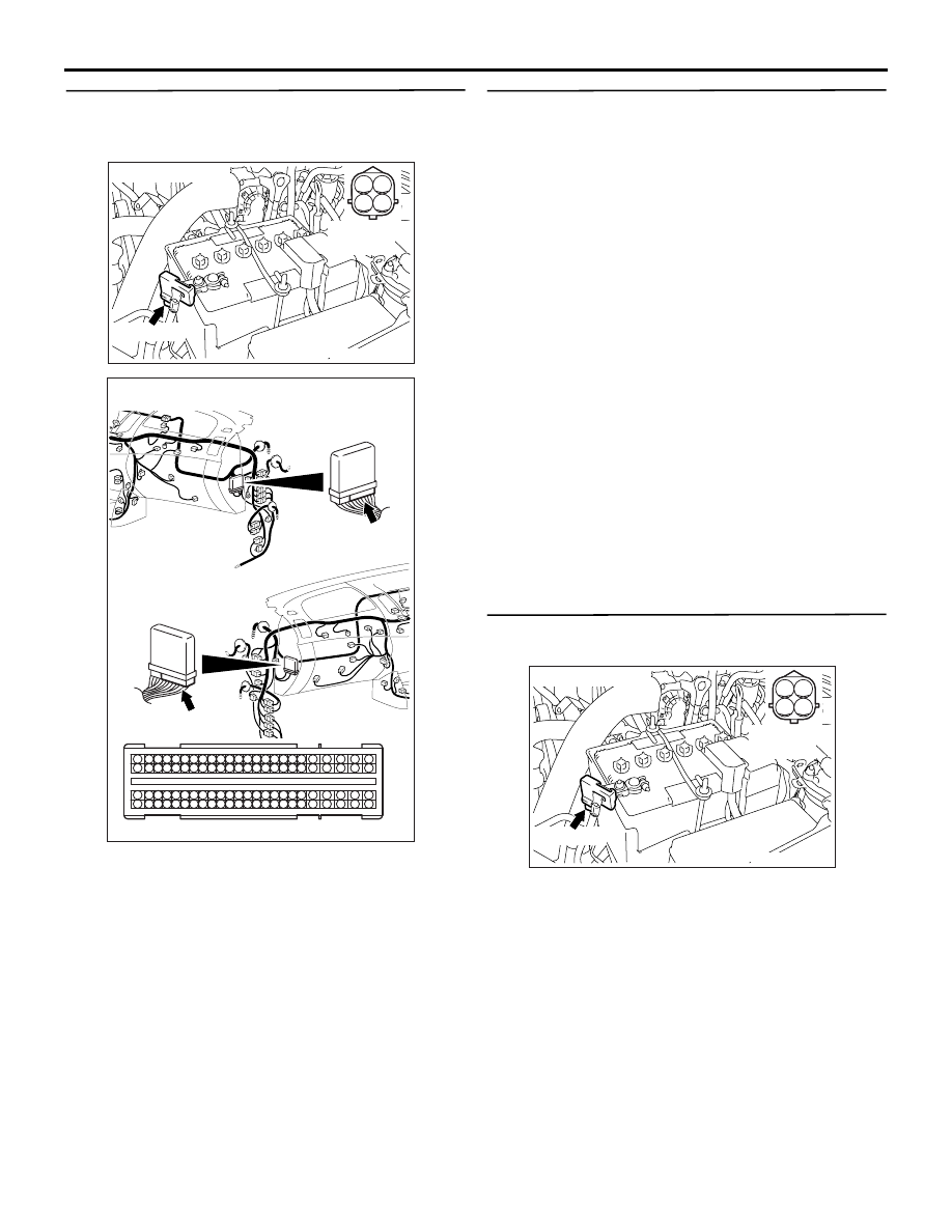
STEP 6. Check harness between A-152 (terminal 
No. 2) battery current sensor connector and C-
105 (terminal No. 39) engine-ECU connector.

• Check output line for open/short circuit.

Q: Is the check result normal?

YES : 

Go to Step 7 .

NO : 

Repair the damaged harness wire.

STEP 7. M.U.T.-III data list

• Item No. 402: Battery temperature sensor

OK: At ambient temperature (atmospheric 
temperature) of battery temperature sensor, 
or equivalent

Q: Is the check result normal?

YES : 

Intermittent malfunction (Refer to GROUP 

00 

− How to Use Troubleshooting/

Inspection Service Points 

− How to Cope 

with Intermittent Malfunctions ).

NO : 

Replace the engine-ECU. When the engine-
ECU is replaced, write the chassis number 
(Refer to GROUP 00 

− Precautions Before 

Service 

− How to Perform Chassis Number 

Writing ). After replacing the engine-ECU, 
register the injector identification code and 
learn fuel injection (Refer to GROUP 00 

− 

Precautions Before Service 

− What The 

Common Rail Engine Learns ). After 
registering the injector identification code, 
carry out the forcible DPF regeneration. 
(Refer to GROUP 17 

− Emission Control − 

Diesel Particulate Filter (DPF) System 

− 

Forcible DPF Regeneration ).

STEP 8. Perform resistance measurement at A-
152 battery current sensor connector.

• Disconnect connector and measure at harness 

side.

• Resistance between terminal No. 3 and earth.

OK: Continuity (2 

 or less)

Q: Is the check result normal?

YES : 

Go to Step 11 .

NO : 

Go to Step 9 .

AKB00274

1

3

2

4

A-152 (GR)

Harness side
connector

Connector: A-152

AB

AKA00089

1

2

3

4

5

6

7

8

9

10

11

12

13

14

15

16

17

18

19

20

21

22

23

24

25

26

27

28

29

30

31

32

33

34

35

36

37

38

39

40

41

42

49

50

51

52

53

54

55

56

57

58

59

60

61

62

63

64

65

66

67

68

69

70

71

72

43

44

45

46

47

48

73

74

75

76

77

78

79

80

81

82

83

84

85

86

87

88

89

90

91

92

93

94

95

96

C-105 (B)

C-105 (B)

<R.H. drive vehicles>

Harness side connector

<L.H. drive vehicles>

Connector: C-105

AB

AKB00274

1

3

2

4

A-152 (GR)

Harness side
connector

Connector: A-152

AB

TROUBLESHOOTING

DIESEL FUEL

13A-257

STEP 9. Connector check: C-103 engine-ECU 
connector

Q: Is the check result normal?

YES : 

Go to Step 10 .

NO : 

Repair or replace the connector.

STEP 10. Check harness between A-152 (terminal 
No. 3) battery current sensor connector and C-
103 (terminal No. 155) engine-ECU connector.

• Check earthing line for open circuit and damage.

Q: Is the check result normal?

YES : 

Go to Step 7 .

NO : 

Repair the damaged harness wire.

AKA00090

101

102

103

104

105

106

107

108

109

110

111

112

113

114

115

118

119

120

121

122

123

124

125

126

127

128

129

130

131

132

133

134

135

136

137

138

139

140

141

142

143

146

147

148

149

150

151

152

153

154

155

156

157

158

117

145

116

144

C-103 (B)

C-103 (B)

<R.H. drive vehicles>

Harness side connector

<L.H. drive vehicles>

Connector: C-103

AB

AKB00274

1

3

2

4

A-152 (GR)

Harness side
connector

Connector: A-152

AB

AKA00090

101

102

103

104

105

106

107

108

109

110

111

112

113

114

115

118

119

120

121

122

123

124

125

126

127

128

129

130

131

132

133

134

135

136

137

138

139

140

141

142

143

146

147

148

149

150

151

152

153

154

155

156

157

158

117

145

116

144

C-103 (B)

C-103 (B)

<R.H. drive vehicles>

Harness side connector

<L.H. drive vehicles>

Connector: C-103

AB

TROUBLESHOOTING

DIESEL FUEL

13A-258

STEP 11. Connector check: C-105 engine-ECU 
connector

Q: Is the check result normal?

YES : 

Go to Step 12 .

NO : 

Repair or replace the connector.

STEP 12. Check harness between A-152 (terminal 
No. 2) battery current sensor connector and C-
105 (terminal No. 39) engine-ECU connector.

• Check output line for damage.

Q: Is the check result normal?

YES : 

Go to Step 7 .

NO : 

Repair the damaged harness wire.

AKA00089

1

2

3

4

5

6

7

8

9

10

11

12

13

14

15

16

17

18

19

20

21

22

23

24

25

26

27

28

29

30

31

32

33

34

35

36

37

38

39

40

41

42

49

50

51

52

53

54

55

56

57

58

59

60

61

62

63

64

65

66

67

68

69

70

71

72

43

44

45

46

47

48

73

74

75

76

77

78

79

80

81

82

83

84

85

86

87

88

89

90

91

92

93

94

95

96

C-105 (B)

C-105 (B)

<R.H. drive vehicles>

Harness side connector

<L.H. drive vehicles>

Connector: C-105

AB

AKB00274

1

3

2

4

A-152 (GR)

Harness side
connector

Connector: A-152

AB

AKA00089

1

2

3

4

5

6

7

8

9

10

11

12

13

14

15

16

17

18

19

20

21

22

23

24

25

26

27

28

29

30

31

32

33

34

35

36

37

38

39

40

41

42

49

50

51

52

53

54

55

56

57

58

59

60

61

62

63

64

65

66

67

68

69

70

71

72

43

44

45

46

47

48

73

74

75

76

77

78

79

80

81

82

83

84

85

86

87

88

89

90

91

92

93

94

95

96

C-105 (B)

C-105 (B)

<R.H. drive vehicles>

Harness side connector

<L.H. drive vehicles>

Connector: C-105

AB

TROUBLESHOOTING

DIESEL FUEL

13A-259

Code No. P0545: No.1 Exhaust Gas Temperature Sensor Circuit Low Input <Euro5>

OPERATION

• A power voltage of 5 V is applied to the No.1 

exhaust gas temperature sensor output terminal 
(terminal No. 1) from the engine-ECU (terminal 
No. 58).

• The power voltage is earthed to the engine-ECU 

(terminal No. 82) from the No.1 exhaust gas tem-
perature sensor (terminal No. 2).

FUNCTION

• The No.1 exhaust gas temperature sensor con-

verts the exhaust gas temperature into a voltage 
and inputs the voltage signal to the engine-ECU.

• Engine-ECU uses this voltage output for DPF 

regeneration control.

• The No.1 exhaust gas temperature sensor is a 

kind of resistor, which has characteristics to 
reduce its resistance as the exhaust gas temper-
ature rises. Therefore, the sensor output voltage 
varies with the exhaust gas temperature, and 
becomes lower as the exhaust gas temperature 
rises.

TROUBLE JUDGMENT

Check Conditions

• Battery positive voltage is 8 − 16 V

• 2 seconds later after the ignition switch has been 

in "ON" position or the engine has started up.

Judgment Criterion

• The No.1 exhaust gas temperature sensor output 

voltage is 0.255 V or less.

PROBABLE CAUSES

• Failed No.1 exhaust gas temperature sensor

• Short circuit in No.1 exhaust gas temperature 

sensor circuit or connector damage

AKB00275

1

2

3

4

5 6 7 8 9

10 1112 13 14 15 16 17 18 19 20 21 22 23 24

25 26

27 28 29 30 31 32 33 34 35 36 37 38 39 40 41 42

49 50 51 52 53 54 55 56 57 58 59 60 61 62 63 64 65 66 67 68 69 70 71 72

43 44 45 46 47 48

73 74 75 76 77 78 79 80 81 82 83 84 85 86 87 88 89 90 91 92 93 94 95 96

1 2

AB

O-G

BR-L

Engine-ECU

No. 1 exhaust gas
temperature sensor

A-149

MU802601

No. 1 Exhaust Gas Temperature Sensor Circuit

2

82

1

58

5 V

C-105

Wire colour code
B: Black  LG: Light green  G: Green  L: Blue  W: White  Y: Yellow  SB: Sky blue  BR: Brown  O: Orange  GR: Grey
R: Red  P: Pink  V: Violet  PU: Purple  SI: Silver


Content   ..  113  114  115  116   ..