Mitsubishi L200. Manual - part 103


  Index      Mitsubishi     Mitsubishi L200 - service repair manual 2012 year


Search            


Content   ..  101  102  103  104   ..


Mitsubishi L200. Manual - part 103


TROUBLESHOOTING

DIESEL FUEL

13A-208

YES : 

Intermittent malfunction (Refer to GROUP 

00 

− How to Use Troubleshooting/

Inspection Service Points 

− How to Cope 

with Intermittent Malfunctions ). 

NO : 

Replace the engine-ECU. When the engine-
ECU is replaced, write the chassis number 
(Refer to GROUP 00 

− Precautions Before 

Service 

− How to Perform Chassis Number 

Writing ). After replacing the engine-ECU, 
register the injector identification code and 
learn fuel injection (Refer to GROUP 00 

− 

Precautions Before Service 

− What The 

Common Rail Engine Learns ). After 
registering the injector identification code, 
carry out the forcible DPF regeneration. 
(Refer to GROUP 17 

− Emission Control − 

Diesel Particulate Filter (DPF) System 

− 

Forcible DPF Regeneration ).

Code No. P0402: EGR Flow Excessive <Euro5>

OPERATION

• Refer to Code No. P0102: Air Flow Sensor Circuit 

Low Input 

P.13A-68

.

• Refer to Code No. P0403: EGR Valve (DC Motor) 

Malfunctio

P.13A-215

.

• Refer to Code No. P0489: EGR Valve Position 

Sensor Circuit Low Input <Euro5> 

P.13A-240

.

FUNCTION

• The engine-ECU monitors the EGR flow rate.

TROUBLE JUDGMENT

Check Conditions

• Engine is running

• Battery positive voltage is 8 − 16 V.

• Vehicle is stopped (transmission: Neutral <M/T>, 

P range <A/T>)

Judgment Criterion

• The EGR flow rate is smaller than target EGR 

flow rate by the rate that is more than the speci-
fied value.

PROBABLE CAUSES

• Failed EGR passage (air suction)

• Harness damage in EGR valve circuit or loose 

connector contact

• Failed EGR valve operation

• Harness damage in air flow sensor circuit or 

loose connector contact

• Failed air flow sensor (abnormal output charac-

teristics)

• Failed engine-ECU

DIAGNOSTIC PROCEDURE

STEP 1. M.U.T.-III diagnosis code

Q: Is the diagnosis code P0403 or P2413 set?

YES : 

Inspection chart for diagnosis codes (Refer 

to 

P.13A-21

).

NO : 

Go to Step 2 .

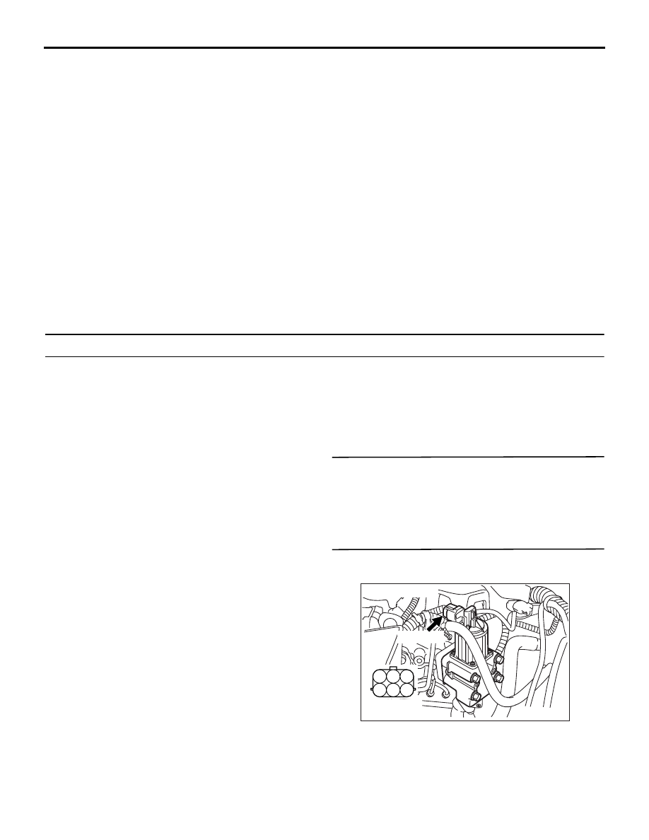
STEP 2. Connector check: A-45 EGR valve 
assembly connector

Q: Is the check result normal?

YES : 

Go to Step 3 .

NO : 

Repair or replace the connector.

AK501331

1

2

3

4

5

6

AB

Harness side 
connector

A-45 (GR)

Connector: A-45

TROUBLESHOOTING

DIESEL FUEL

13A-209

STEP 3. Connector check: C-103 and C-105 
engine-ECU connectors

Q: Is the check result normal?

YES : 

Go to Step 4 .

NO : 

Repair or replace the connector.

STEP 4. Check harness between C-103 (terminal 
No. 115) engine-ECU connector and A-45 
(terminal No. 6) EGR valve assembly connector.

• Check output line for damage.

Q: Is the check result normal?

YES : 

Go to Step 5 .

NO : 

Repair the damaged harness wire.

AKB00270

1

2

3

4

5

6

7

8

9

10

11

12

13

14

15

16

17

18

19

20

21

22

23

24

25

26

27

28

29

30

31

32

33

34

35

36

37

38

39

40

41

42

49

50

51

52

53

54

55

56

57

58

59

60

61

62

63

64

65

66

67

68

69

70

71

72

43

44

45

46

47

48

73

74

75

76

77

78

79

80

81

82

83

84

85

86

87

88

89

90

91

92

93

94

95

96

101

102

103

104

105

106

107

108

109

110

111

112

113

114

115

118

119

120

121

122

123

124

125

126

127

128

129

130

131

132

133

134

135

136

137

138

139

140

141

142

143

146

147

148

149

150

151

152

153

154

155

156

157

158

117

145

116

144

C-105 (B)

C-103 (B)

C-105 (B)

C-103 (B)

<R.H. drive vehicles>

C-105 Harness side connector

C-103 Harness side connector

<L.H. drive vehicles>

Connectors: C-103, C-105

AB

AKA00090

101

102

103

104

105

106

107

108

109

110

111

112

113

114

115

118

119

120

121

122

123

124

125

126

127

128

129

130

131

132

133

134

135

136

137

138

139

140

141

142

143

146

147

148

149

150

151

152

153

154

155

156

157

158

117

145

116

144

C-103 (B)

C-103 (B)

<R.H. drive vehicles>

Harness side connector

<L.H. drive vehicles>

Connector: C-103

AB

AK501331

1

2

3

4

5

6

AB

Harness side 
connector

A-45 (GR)

Connector: A-45

TROUBLESHOOTING

DIESEL FUEL

13A-210

STEP 5. Check harness between C-103 (terminal 
No. 130) engine-ECU connector and A-45 
(terminal No. 4) EGR valve assembly connector.

• Check output line for damage.

Q: Is the check result normal?

YES : 

Go to Step 6 .

NO : 

Repair the damaged harness wire.

STEP 6. Check harness between C-105 (terminal 
No. 81) engine-ECU connector and A-45 (terminal 
No. 2) EGR valve assembly connector.

• Check earthing line for damage.

Q: Is the check result normal?

YES : 

Go to Step 7 .

NO : 

Repair the damaged harness wire.

AKA00090

101

102

103

104

105

106

107

108

109

110

111

112

113

114

115

118

119

120

121

122

123

124

125

126

127

128

129

130

131

132

133

134

135

136

137

138

139

140

141

142

143

146

147

148

149

150

151

152

153

154

155

156

157

158

117

145

116

144

C-103 (B)

C-103 (B)

<R.H. drive vehicles>

Harness side connector

<L.H. drive vehicles>

Connector: C-103

AB

AK501331

1

2

3

4

5

6

AB

Harness side 
connector

A-45 (GR)

Connector: A-45

AKA00089

1

2

3

4

5

6

7

8

9

10

11

12

13

14

15

16

17

18

19

20

21

22

23

24

25

26

27

28

29

30

31

32

33

34

35

36

37

38

39

40

41

42

49

50

51

52

53

54

55

56

57

58

59

60

61

62

63

64

65

66

67

68

69

70

71

72

43

44

45

46

47

48

73

74

75

76

77

78

79

80

81

82

83

84

85

86

87

88

89

90

91

92

93

94

95

96

C-105 (B)

C-105 (B)

<R.H. drive vehicles>

Harness side connector

<L.H. drive vehicles>

Connector: C-105

AB

AK501331

1

2

3

4

5

6

AB

Harness side 
connector

A-45 (GR)

Connector: A-45

TROUBLESHOOTING

DIESEL FUEL

13A-211

STEP 7. Check harness between C-105 (terminal 
No. 71) engine-ECU connector and A-45 (terminal 
No. 3) EGR valve assembly connector.

• Check power supply line for damage.

Q: Is the check result normal?

YES : 

Go to Step 8 .

NO : 

Repair the damaged harness wire.

STEP 8. Check harness between C-105 (terminal 
No. 57) engine-ECU connector and A-45 (terminal 
No. 1) EGR valve assembly connector.

• Check output line for damage.

Q: Is the check result normal?

YES : 

Go to Step 9 .

NO : 

Repair the damaged harness wire.

STEP 9. Check EGR valve itself.

• Check EGR valve itself [Refer to GROUP 17 − 

Emission Control 

− Exhaust Gas Recirculation 

(EGR) System 

− EGR Valve (DC motor) Check ].

Q: Is the check result normal?

YES : 

Go to Step 10 .

NO : 

Replace the EGR valve assembly.

AKA00089

1

2

3

4

5

6

7

8

9

10

11

12

13

14

15

16

17

18

19

20

21

22

23

24

25

26

27

28

29

30

31

32

33

34

35

36

37

38

39

40

41

42

49

50

51

52

53

54

55

56

57

58

59

60

61

62

63

64

65

66

67

68

69

70

71

72

43

44

45

46

47

48

73

74

75

76

77

78

79

80

81

82

83

84

85

86

87

88

89

90

91

92

93

94

95

96

C-105 (B)

C-105 (B)

<R.H. drive vehicles>

Harness side connector

<L.H. drive vehicles>

Connector: C-105

AB

AK501331

1

2

3

4

5

6

AB

Harness side 
connector

A-45 (GR)

Connector: A-45


Content   ..  101  102  103  104   ..