Mitsubishi L200. Manual - part 97
TROUBLESHOOTING
DIESEL FUEL
13A-184
OPERATION
• A power voltage of 5 V is applied to the crank
angle sensor power terminal (terminal No. 3)
from the engine-ECU (terminal No. 68) and
earthed to engine-ECU (terminal No. 91) from the
crank angle sensor (terminal No. 1).
• The sensor signal is inputted to the engine-ECU
(terminal No. 67) from the crank angle sensor
output terminal (terminal No. 2).
FUNCTION
• The crank angle sensor detects the crank angle
(position) and inputs a pulse signal to the engine-
ECU.
• In response to the signal, the engine ECU detects
the engine speed, controls the fuel injection tim-
ing and fuel injection quantity, etc.
TROUBLE JUDGMENT
Check Condition
• Battery positive voltage is 6 − 16 V.
Judgment Criterion
• The number of output pulses from the crank
angle sensor per engine rotation is one or less.
PROBABLE CAUSES
• Failed crank angle sensor
• Open/short circuit in crank angle sensor circuit or
loose connector contact
• Failed engine-ECU
DIAGNOSIS PROCEDURE
STEP 1. M.U.T.-III data list
• Refer to Data List Reference Table
a. Item 2: Engine revolution
Q: Is the check result normal?
YES :
Intermittent malfunction (Refer to GROUP
00
− How to Use Troubleshooting/
Inspection Service Points
− How to Cope
with Intermittent Malfunctions ).
NO :
Go to Step 2 .
STEP 2. Connector check: A-07 crank angle
sensor connector
Q: Is the check result normal?
YES :
Go to Step 3 .
NO :
Repair or replace the connector.
STEP 3. Perform voltage measurement at A-07
crank angle sensor connector.
• Use special tool test harness (MB991709) to con-
nect connector, and measure at pick-up harness.
• Ignition switch: ON
• Voltage between terminal No. 2 and earth.
OK: 4.9
− 5.1 V
Q: Is the check result normal?
YES :
Go to Step 9 .
NO :
Go to Step 4 .
AK501329
1
2
3
AB
Harness side
connector
A-07 (B)
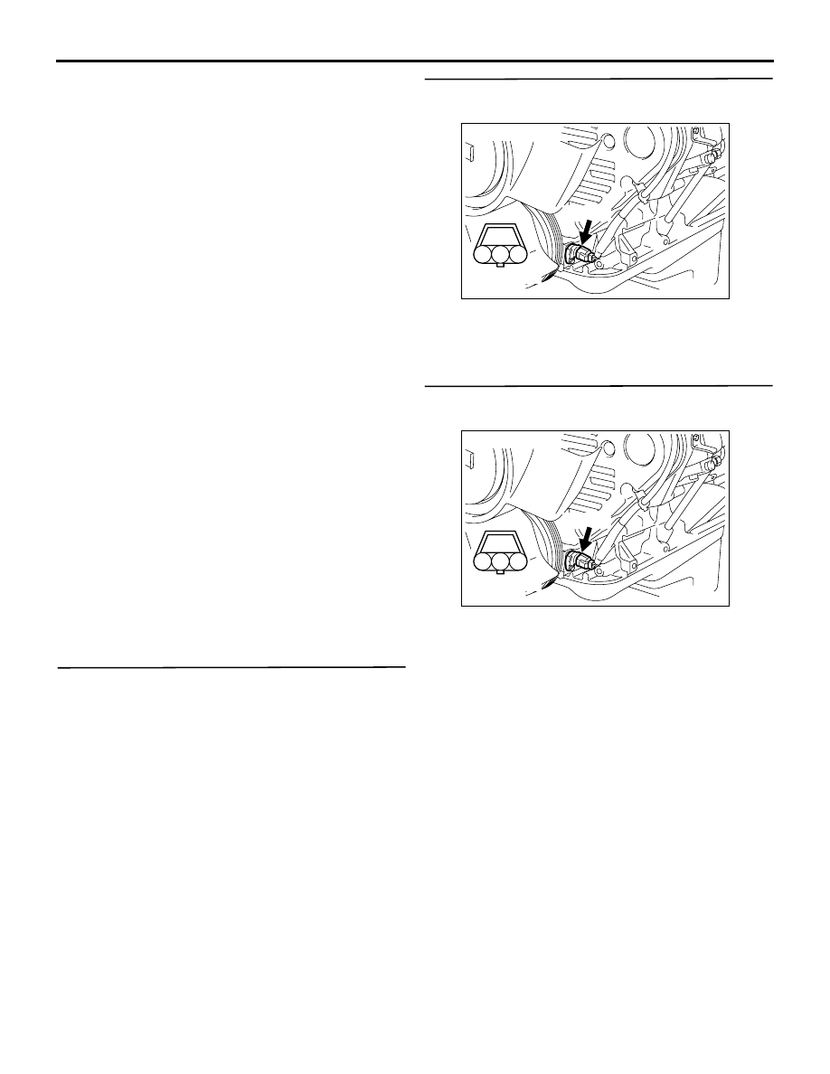
Connector: A-07
AK501329
1
2
3
AB
Harness side
connector
A-07 (B)
Connector: A-07