Mitsubishi L200. Manual - part 68
TROUBLESHOOTING
DIESEL FUEL
13A-68
FUNCTION
• The air flow sensor outputs pulse signal that var-
ies in accordance with the intake air volume.
• In response to the signal, the engine-ECU con-
trols EGR control, etc.
TROUBLE JUDGMENT
Check Conditions
• Battery positive voltage is 8 − 16 V
• 2 seconds later after the ignition switch has been
in "ON" position or the engine has started up.
Judgment Criterion
• The air flow sensor output voltage is 0.50 V or
less.
PROBABLE CAUSES
• Failed air flow sensor
• Open/short circuit or harness damage in air flow
sensor circuit or loose connector contact
• Failed engine-ECU
DIAGNOSIS PROCEDURE
STEP 1. M.U.T.-III data list
• Refer to Data List Reference Table
.
a. Item 114: Air flow sensor
Q: Is the check result normal?
YES :
Intermittent malfunction (Refer to GROUP
00
− How to Use Troubleshooting/
Inspection Service Points
− How to Cope
with Intermittent Malfunctions ).
NO :
Go to Step 2 .
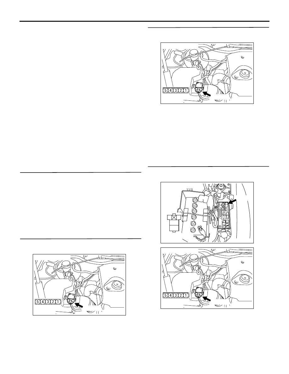
STEP 2. Connector check: A-135 air flow sensor
connector
Q: Is the check result normal?
YES :
Go to Step 3 .
NO :
Repair or replace the connector.
STEP 3. Perform voltage measurement at A-135
air flow sensor connector.
• Disconnect connector, and measure at harness
side.
• Ignition switch: ON
• Voltage between terminal No. 5 and earth.
OK: System voltage
Q: Is the check result normal?
YES :
Go to Step 5 .
NO :
Go to Step 4 .
STEP 4. Connector check: A-20X engine control
relay connector
Q: Is the check result normal?
AKA00399
AB
Harness side
connector
A-135 (B)
Connector: A-135
AKA00399
AB
Harness side
connector
A-135 (B)
Connector: A-135
AK501321
2
1
3
4
Relay box's side
connector
A-20X
Connector: A-20X
AC
AKA00399
AB
Harness side
connector
A-135 (B)
Connector: A-135