Mitsubishi L200. Manual - part 67


  Index      Mitsubishi     Mitsubishi L200 - service repair manual 2012 year


Search            


Content   ..  65  66  67  68   ..


Mitsubishi L200. Manual - part 67


TROUBLESHOOTING

DIESEL FUEL

13A-64

• Failed rail pressure sensor.

• Harness damage in rail pressure sensor circuit or 

loose connector contact.

• Failed engine-ECU

DIAGNOSTIC PROCEDURE

STEP 1. M.U.T.-III diagnosis code

Q: Is any other diagnosis code than P0093 set?

YES : 

Inspection chart for diagnosis codes (Refer 

to 

P.13A-21

).

NO : 

Go to Step 2 .

STEP 2. Detection of fuel line leakage

• Check whether fuel is leaking from a high-pres-

sure fuel line.

Q: Is the check result normal?

YES : 

Go to Step 3 .

NO : 

Replace the parts of an abnormal location.

STEP 3. Release the air from the fuel line.

• After releasing the air from the fuel line, continue 

idle operation for about five minutes and recheck 
for trouble symptoms.

Q: Does the trouble symptom persist?

YES : 

Go to Step 4 .

NO : 

The check is end.

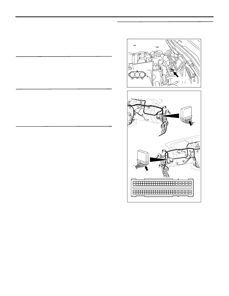
STEP 4. Connector check: A-44 rail pressure 
sensor connector and C-105 engine-ECU 
connector.

Q: Are the check results normal?

YES : 

Go to Step 5 .

NO : 

Repair or replace the connector.

AK501327

1

2

3

AB

A-44 (B)

Harness side 
connector

Connector: A-44

AKA00089

1

2

3

4

5

6

7

8

9

10

11

12

13

14

15

16

17

18

19

20

21

22

23

24

25

26

27

28

29

30

31

32

33

34

35

36

37

38

39

40

41

42

49

50

51

52

53

54

55

56

57

58

59

60

61

62

63

64

65

66

67

68

69

70

71

72

43

44

45

46

47

48

73

74

75

76

77

78

79

80

81

82

83

84

85

86

87

88

89

90

91

92

93

94

95

96

C-105 (B)

C-105 (B)

<R.H. drive vehicles>

Harness side connector

<L.H. drive vehicles>

Connector: C-105

AB

TROUBLESHOOTING

DIESEL FUEL

13A-65

STEP 5. Check harness between A-44 (terminal 
No. 1) rail pressure sensor connector and C-105 
(terminal No. 70) engine-ECU connector.

NOTE: Before checking harness, check intermediate 
connector A-131, and repair if necessary.

• Check power supply line for damage.

Q: Is the check result normal?

YES : 

Go to Step 6 .

NO : 

Repair the damaged harness wire.

STEP 6. Check harness between A-44 (terminal 
No. 2) rail pressure sensor connector and C-105 
(terminal No. 64) engine-ECU connector.

NOTE: Before checking harness, check intermediate 
connector A-131, and repair if necessary.

• Check output line for damage.

Q: Is the check result normal?

YES : 

Go to Step 7 .

NO : 

Repair the damaged harness wire.

AK501327

1

2

3

AB

A-44 (B)

Harness side 
connector

Connector: A-44

AKA00089

1

2

3

4

5

6

7

8

9

10

11

12

13

14

15

16

17

18

19

20

21

22

23

24

25

26

27

28

29

30

31

32

33

34

35

36

37

38

39

40

41

42

49

50

51

52

53

54

55

56

57

58

59

60

61

62

63

64

65

66

67

68

69

70

71

72

43

44

45

46

47

48

73

74

75

76

77

78

79

80

81

82

83

84

85

86

87

88

89

90

91

92

93

94

95

96

C-105 (B)

C-105 (B)

<R.H. drive vehicles>

Harness side connector

<L.H. drive vehicles>

Connector: C-105

AB

TROUBLESHOOTING

DIESEL FUEL

13A-66

STEP 7. Check harness between A-44 (terminal 
No. 3) rail pressure sensor connector and C-105 
(terminal No. 88) engine-ECU connector.

NOTE: Before checking harness, check intermediate 
connector A-131, and repair if necessary.

• Check earthing line for damage.

Q: Is the check result normal?

YES : 

Go to Step 8 .

NO : 

Repair the damaged harness wire.

STEP 8. Detection of fuel leakage from injector 
body

• Remove the injector. Check whether there is the 

evidence of the fuel leakage from the injector 
body.

Q: Is the check result normal?

YES : 

Go to Step 9 .

NO : 

Replace the abnormal injector. After 
replacing the injector, register the injector 
identification code and learn fuel injection. 
(Refer to GROUP 00 

− Precautions Before 

Service 

− What The Common Rail Engine 

Learns ). 

STEP 9. Replace the common rail assembly and 
fuel injection tubes.

• After replacing the common rail assembly and 

fuel injection tubes, re-check the trouble symp-
toms.

Q: Does the trouble symptom persist?

YES : 

Replace the engine-ECU. When the engine-

ECU is replaced, write the chassis number 
(Refer to GROUP 00 

− Precautions Before 

Service 

− How to Perform Chassis Number 

Writing ). After replacing the engine-ECU, 
register the injector identification code and 
learn fuel injection (Refer to GROUP 00 

− 

Precautions Before Service 

− What The 

Common Rail Engine Learns ). After 
registering the injector identification code, 
the vehicle equipped with the DPF carries 
out the forcible DPF regeneration. (Refer to 
GROUP 17 

− Emission Control − Diesel 

Particulate Filter (DPF) System 

− Forcible 

DPF Regeneration ).

NO : 

The check is end.

AK501327

1

2

3

AB

A-44 (B)

Harness side 
connector

Connector: A-44

AKA00089

1

2

3

4

5

6

7

8

9

10

11

12

13

14

15

16

17

18

19

20

21

22

23

24

25

26

27

28

29

30

31

32

33

34

35

36

37

38

39

40

41

42

49

50

51

52

53

54

55

56

57

58

59

60

61

62

63

64

65

66

67

68

69

70

71

72

43

44

45

46

47

48

73

74

75

76

77

78

79

80

81

82

83

84

85

86

87

88

89

90

91

92

93

94

95

96

C-105 (B)

C-105 (B)

<R.H. drive vehicles>

Harness side connector

<L.H. drive vehicles>

Connector: C-105

AB

TROUBLESHOOTING

DIESEL FUEL

13A-67

Code No. P0102: Air flow Sensor Circuit Low Input

OPERATION

• Power is supplied by the engine control relay (ter-

minal No. 3) to the air flow sensor (terminal No. 
5), and the air flow sensor (terminal No. 4) is 
earthed through the engine-ECU (terminal No. 
155).

• The air flow sensor (terminal No. 3) outputs a 

sensor signal, which is input into the engine-ECU 
(terminal No. 140).

AKA00355

1

2

3
4

101 102

103104 105 106107 108109 110 111112 113 114115

118119 120 121122 123124 125126127 128 129130

131132 133 134135 136137 138139140 141142 143

146147 148 149150 151152 153154155 156 157158

117

145

116

144

101 102

103104 105 106107 108109 110 111112 113 114115

118119 120 121122 123124 125126127 128 129130

131132 133 134135 136137 138139140 141142 143

146147 148 149150 151152 153154155 156 157158

117

145

116

144

5

4

3

2

1

W-R

W-B

W-B

W-B

Fusible link

BR-B

W-R

R

A-20X

Engine

control

relay

Relay

box

Air flow sensor

Engine-ECU

140

3

155

5

4

1

3

A-115

4

3

2

Air Flow Sensor Circuit

C-103

A-135

AB

Wire colour code
B: Black  LG: Light green  G: Green  L: Blue  W: White  Y: Yellow  SB: Sky blue  BR: Brown  O: Orange  GR: Grey
R: Red  P: Pink  V: Violet  PU: Purple  SI: Silver

To engine-ECU

OFF

ON

5 V

10

23

20A

Heat
sensitizing
resistance


Content   ..  65  66  67  68   ..