Mitsubishi L200. Manual - part 27


  Index      Mitsubishi     Mitsubishi L200 - service repair manual 2012 year


Search            


Content   ..  25  26  27  28   ..


Mitsubishi L200. Manual - part 27


CRANKSHAFT OIL SEAL

ENGINE MECHANICAL

11A-36

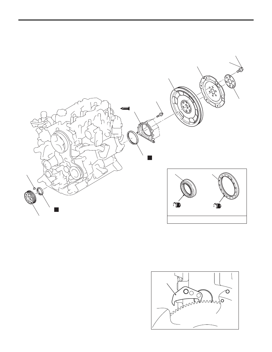
REMOVAL AND INSTALLATION <A/T>

M1112003104220

ACB00630

1

2

N

6

135 ± 5 N·m

11 ± 1 N·m

4

5

N

7

8

9

3

9

(Lip section)

(Lip section)

Engine oil

AB

Crankshaft front oil seal removal 
steps 

Timing belt, timing belt B (Refer to 

P.11A-43

)

>>

E

<<

1.

Crankshaft B sprocket

2.

Crankshaft key

>>

D

<<

3.

Crankshaft front oil seal
Crankshaft rear oil seal removal 
steps 

Transmission assembly (Refer to 
GROUP 23A 

− Transmission 

Assembly 

P.23A-135

) <4A/T>

Transmission assembly (Refer to 
GROUP 23A 

− Transmission 

Assembly 

P.23A-139

) <5A/T>

<<

A

>>

>>

C

<<

4.

Drive plate bolt

5.

Adapter plate

6.

Drive plate

7.

Inertia ring assembly

>>

B

<<

8.

Oil seal case assembly

>>

A

<<

9.

Crankshaft rear oil seal

REMOVAL SERVICE POINT

<<A>> DRIVE PLATE BOLT REMOVAL

AC802013

MB991883

AB

Crankshaft rear oil seal removal 
steps (Continued)

CRANKSHAFT OIL SEAL

ENGINE MECHANICAL

11A-37

1. Use special tool flywheel stopper (MB991883) to 

secure the inertia ring assembly.

2. Remove the drive plate bolts.

INSTALLATION SERVICE POINTS

>>A<< CRANKSHAFT REAR OIL SEAL INSTAL-
LATION
1. Apply a small amount of engine oil to the entire 

inner diameter of the oil seal lip.

AK503243AB

8.5 mm

Oil seal

Oil seal case

MB992147

2. Use special tool oil seal installer (MB992147) to 

press-fit the crankshaft rear oil seal.

3. Press-fit the crankshaft rear oil seal into the oil 

seal case assembly to have the dimension shown 
in the illustration.

>>B<< CRANKSHAFT REAR OIL SEAL CASE 
ASSEMBLY INSTALLATION
1. Remove completely old sealant remaining on the 

crankshaft rear oil seal case assembly and 
cylinder block.

AC503164 AD

Crankshaft
rear oil seal
case assembly

2. Apply a continuous bead of the specified sealant 

to the crankshaft rear oil seal case assembly 
mating surface as shown.

Specified sealant: ThreeBond 1207F

NOTE: Install the crankshaft rear oil seal case 
assembly immediately applying sealant.

CAUTION

After the installation, until a sufficient period of 
time (one hour or more) elapses, do not apply the 
oil or water to the sealant application area or 
start the engine.
3. Applying an appropriate amount of engine oil to 

the entire circumference of its crankshaft oil seal 
rear lip portion, and then set the crankshaft rear 
oil seal case assembly to the cylinder block and 
tighten the mounting bolts to the specified torque.

Tightening torque: 11 

± 1 Nm

>>C<< DRIVE PLATE BOLT INSTALLATION

AC802014

MB991883

AB

1. Use special tool flywheel stopper (MB991883) to 

secure the inertia ring assembly in the same 
manner as removal.

2. Tighten the drive plate bolts to the specified 

torque.

Tightening torque: 135 

± 5 Nm

>>D<< CRANKSHAFT FRONT OIL SEAL 
INSTALLATION

AC102329AI

MD998383

(Engine oil)

(Oil applied to the
circumference)

Crankshaft
front oil seal

Crankshaft

MD998382

1. Apply a small amount of engine oil to the outer 

diameter of special tool crankshaft front oil seal 
guide (MD998383) and install it to the crankshaft.

2. Apply a small amount of engine oil to the entire 

inner diameter of the oil seal lip.

3. Use special tool crankshaft front oil seal installer 

(MD998382) to press-fit the crankshaft front oil 
seal.

CRANKSHAFT OIL SEAL

ENGINE MECHANICAL

11A-38

>>E<< CRANKSHAFT B SPROCKET 
INSTALLATION

AC502148

AB

: Clean
: Clean and degrease

Crankshaft B sprocket

Engine front

Front case

Crankshaft

1. Clean or degrease the oil pump case, the 

crankshaft and the crankshaft B sprocket as 
shown.
NOTE: Also clean the degreased surfaces.

2. Install the crankshaft B sprocket in the direction 

shown in the illustration.

CYLINDER HEAD GASKET

ENGINE MECHANICAL

11A-39

CYLINDER HEAD GASKET

REMOVAL AND INSTALLATION

M1112004005081

Pre-removal Operation
• Engine Oil Draining (Refer to GROUP 12 − On-vehicle 

Service, Engine Oil Replacement 

P.12-4

).

• Fuel Injector Removal (Refer to GROUP 13A − Fuel Injec-

tor 

P.13A-598

).

• Common Rail Assembly Removal (Refer to GROUP 13A 

− Common Rail and Supply Pump 

P.13A-604

).

• Turbocharger Assembly and Exhaust Manifold Removal 

(Refer to GROUP 15 

− Turbocharger Assembly 

P.15-19

<Except Euro5>.

• Turbocharger Assembly and Exhaust Manifold Removal 

(Refer to GROUP 15 

− Turbocharger Assembly 

P.15-21

<Euro5>.

• Timing Belt Removal (Refer to 

P.11A-43

).

Post-installation Operation
• Timing Belt Installation (Refer to 

P.11A-43

).

• Turbocharger Assembly and Exhaust Manifold Installation 

(Refer to GROUP 15 

− Turbocharger Assembly 

P.15-19

<Except Euro5>.

• Turbocharger Assembly and Exhaust Manifold Installation 

(Refer to GROUP 15 

− Turbocharger Assembly 

P.15-21

<Euro5>.

• Common Rail Assembly Installation (Refer to GROUP 

13A 

− Common Rail and Supply Pump 

P.13A-604

).

• Fuel Injector Installation (Refer to GROUP 13A − Fuel 

Injector 

P.13A-598

).

• Engine Oil Refilling (Refer to GROUP 12 − On-vehicle 

Service, Engine Oil Replacement 

P.12-4

).

AC502177AE

2

1

3

4

5

6

9

7

10

11

10 ± 2 N·m

8

5.0 ± 1.0 N·m
<Except Euro5>

88 ± 10 N·m

24 ± 4 N·m

78 ± 2 N·m to


0 N·m to


29 ± 2 N·m to +90˚ to


+90˚ 

(Cold engine)

(Engine oil)

Removal steps 

1.

Engine coolant temperature sensor 
connector 

2.

Engine coolant temperature gauge 
unit connector 

3.

Control wiring harness connection 

<<A>>

>>D<<

4.

Radiator upper hose connection

5.

Oil hose connection

<<

B

>>

>>

C

<<

6.

Camshaft sprocket

7.

Timing belt rear cover

<<

C

>>

8.

Power steering oil pump assembly

<<

D

>>

>>

B

<<

9.

Cylinder head bolt

10. Cylinder head assembly

>>

A

<<

11. Cylinder head gasket

Removal steps (Continued)


Content   ..  25  26  27  28   ..