Mitsubishi L200. Manual - part 24


  Index      Mitsubishi     Mitsubishi L200 - service repair manual 2012 year


Search            


Content   ..  22  23  24  25   ..


Mitsubishi L200. Manual - part 24


AC501917

Sub gear

Inlet camshaft

2.3 – 2.8 mm

2.3 – 2.8 mm

Dowel pin

Dowel pin

AB

CAMSHAFT AND VALVE STEM SEAL

ENGINE MECHANICAL

11A-24

2. Press fit the dowel pin into the inlet camshaft and 

sub gear so that the dimension becomes as 
shown in the figure.

AC501918AB

C-spring

Dowel pin

Inlet camshaft

3. After contacting the C-spring with the dowel pin as 

shown in the figure, set to the inlet camshaft.

AC501918AC

C-spring

Dowel pin

Inlet camshaft

A

4. Set the sub gear to the inlet camshaft so that the 

sub gear dowel pin is inside the A range between 
the C-spring and inlet camshaft dowel pin as 
shown in the figure.

5. Assemble the wave washer and the snap ring to 

the inlet camshaft.

>>H<< INLET CAMSHAFT ASSEMBLY 
INSTALLATION

AC501919 AB

Inlet camshaft

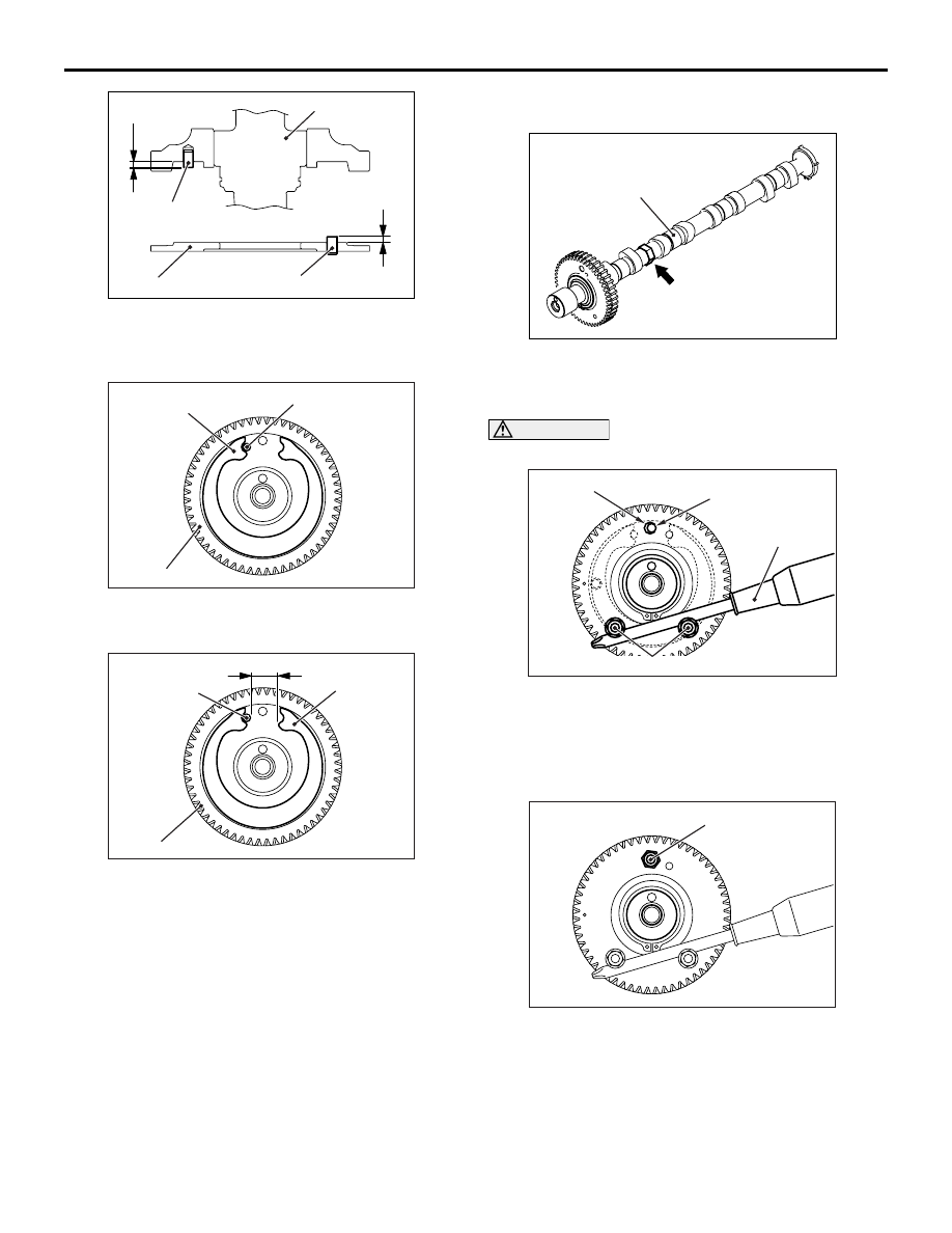
1. Fix the hexagonal area of inlet camshaft assembly 

using a vice or other devices.

CAUTION

Avoid turning the sub gear than necessary.

AC501920AB

Thread hole of
camshaft (M6)

Hole of sub gear (M8)

Screwdriver

Flange bolts (M6 × 20)

2. Set the flange bolts (M6 x 20) to 2 locations of sub 

gear. Then, using a screwdriver, turn the sub gear 
clockwise until the sub gear hole (M8) and the 
threaded hole (M6) of inlet camshaft gear match 
as shown in the figure.

AC501921AB

Bolt (M6 × 20)

3. Temporarily fix the sub gear using the bolt (M6 x 

20). At this time, screw in until the bolt head is in 
contact with the sub gear.

4. Remove the 2 flange bolts (M6 x 20) installed in 

the step 2.

CAMSHAFT AND VALVE STEM SEAL

ENGINE MECHANICAL

11A-25

5. Remove from the vice or other devices the inlet 

camshaft assembly to which the sub gear being 
temporarily fixed. Then, apply the engine oil to the 
cam face, journal section, thrust face, and gear 
teeth face of inlet camshaft assembly.

AC501922AB

Inlet camshaft

Timing mark

Exhaust
camshaft

6. Set the timing mark of the inlet camshaft 

assembly and exhaust camshaft in the position 
shown in the illustration.

>>I<< LEFT CAMSHAFT BEARING CAP/O-RING/
INLET OIL PIPE ASSEMBLY/FRONT LEFT 
CAMSHAFT BEARING CAP INSTALLATION
1. Place the left camshaft bearing cap onto the 

camshaft journal.

2. Apply the engine oil to the O-ring of the inlet oil 

pipe assembly, and insert the tip of the inlet oil 
pipe assembly into the cylinder head. Then, place 
the pipe onto the left camshaft bearing cap.

CAUTION

After the installation, until a sufficient period of 
time (one hour or more) elapses, do not apply the 
oil or water to the sealant application area or 
start the engine.

AC501923AB

Cylinder head
assembly

Front left
camshaft
bearing cap

3. Apply specified sealant to the matching area of 

the cylinder head assembly and the front left 
camshaft bearing cap as shown, and install the 
left camshaft bearing cap to the cylinder head 
assembly.

Specified sealant: 3M ATD Part No.8660

NOTE: Install the front left camshaft bearing cap 
immediately after applying sealant.

AC501924AB

10

9

8

7

6

5

2

1

Engine front

Left camshaft bearing cap

4

3

Front left camshaft
bearing cap

4. Tighten the mounting bolts of the left camshaft 

bearing cap and front left camshaft bearing cap to 
the specified torque in the order shown in the 
figure. Then, fix the left camshaft bearing cap, 
inlet oil pipe assembly, and front left camshaft 
bearing cap to the cylinder head.

Tightening torque:

11 

± 1 Nm (Left camshaft bearing cap mount-

ing bolts)

20 

± 1 Nm (Front left camshaft bearing cap 

mounting bolts)

5. Remove the bolt (M6 x 20) used to temporarily fix 

the sub gear of inlet camshaft assembly.

>>J<< CAMSHAFT OIL SEAL INSTALLATION

AC102323AC

MD998713

Camshaft oil seal

(Engine oil)

1. Apply engine oil to the entire inner diameter of the 

oil seal lip.

CAMSHAFT AND VALVE STEM SEAL

ENGINE MECHANICAL

11A-26

2. Use special tool camshaft oil seal installer 

(MD998713) to press-fit the oil seal as shown. 

>>K<< CAMSHAFT SPROCKET INSTALLATION

AC507554

MD998719

MB990767

AB

1. Use the following special tool as during removal to 

hold the camshaft sprocket.

• Front hub and flange yoke holder (MB990767)

• Pin (MD998719)

2. Tighten the camshaft sprocket mounting bolt to 

the specified torque.

Tightening torque: 88 

± 10 Nm

OIL PAN AND OIL STRAINER

ENGINE MECHANICAL

11A-27

OIL PAN AND OIL STRAINER

REMOVAL AND INSTALLATION <2WD 
(EXCEPT HIGH RIDER)>

M1112008301004

CAUTION

At the time of factory shipment or when the engine is overhauled, liquid gasket is used for the engine 
oil pan gasket. Use the replacement engine oil pan gasket since the sealed surface may interfere with 
surrounding parts, causing engine oil leak when the engine oil pan is installed on the vehicle using 
the liquid gasket.

Pre-removal Operation
• Engine Room Under Cover Removal (Refer to GROUP 51 

− Under Cover 

P.51-32

).

• Engine Oil Draining (Refer to GROUP 12 − On-vehicle 

Service, Engine Oil Replacement 

P.12-4

).

Post-installation Operation
• Engine Oil Refilling (Refer to GROUP 12 − On-vehicle 

Service, Engine Oil Replacement 

P.12-4

).

• Engine Room Under Cover Installation (Refer to GROUP 

51 

− Under Cover 

P.51-32

).

AC506493

19 ± 3 N·m

6

7

N

10

11

AC

3

1

2

N

4

N

5

19 ± 3 N·m

39 ± 5 N·m

9.0 ± 3.0 N·m

19 ± 3 N·m

9.0 ± 1.0 N·m

48 ± 6 N·m

9

(Engine oil)

8

N

11 ± 1 N·m

Removal steps 

1.

Engine oil level gauge and guide 
assembly

2.

O-ring

3.

Bell housing cover

4.

Engine oil pan drain plug

>>

B

<<

5.

Engine oil pan drain plug gasket

Removal steps (Continued)


Content   ..  22  23  24  25   ..