Mitsubishi L200. Manual - part 23
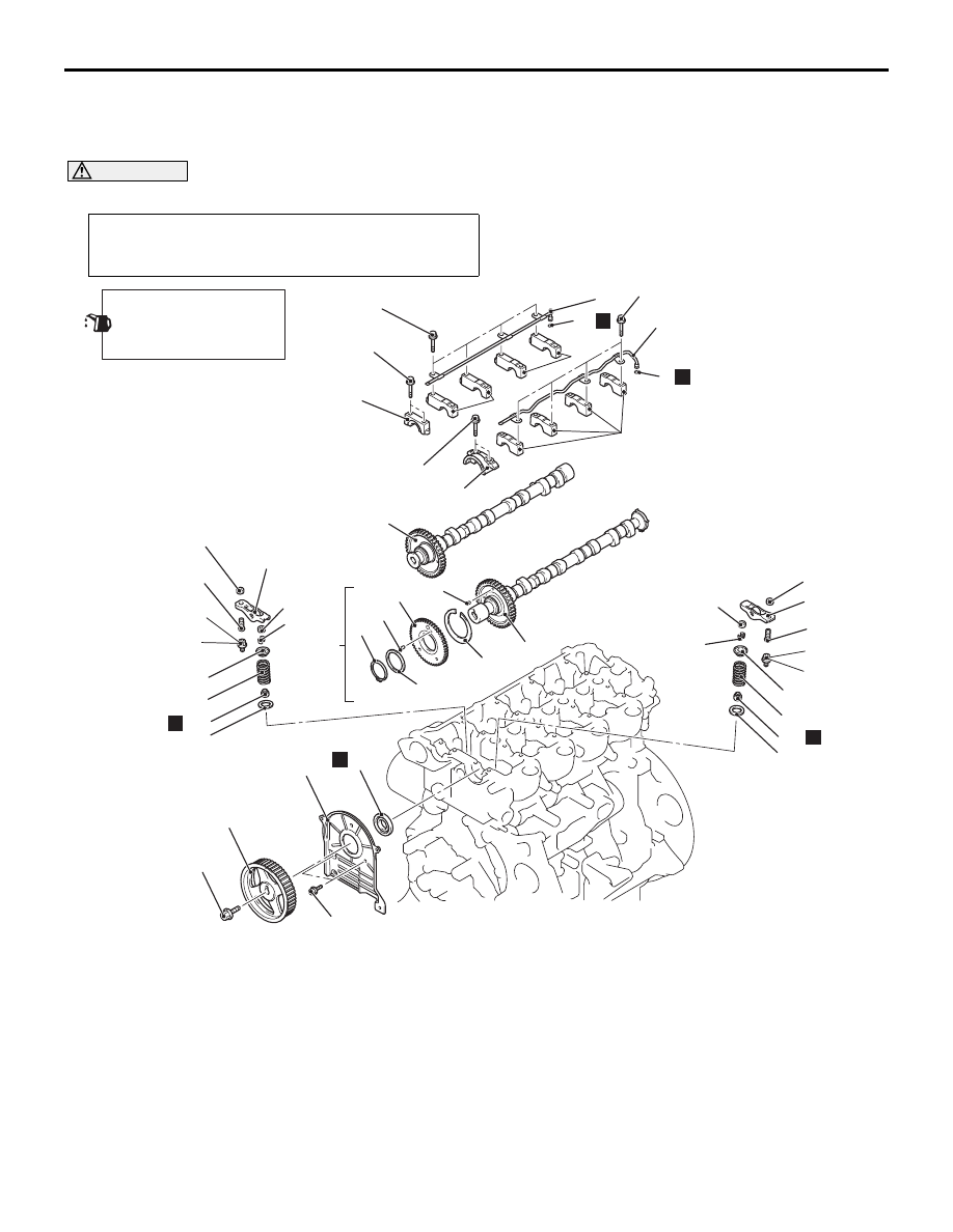
CAMSHAFT AND VALVE STEM SEAL
ENGINE MECHANICAL
11A-20
CAMSHAFT AND VALVE STEM SEAL
REMOVAL AND INSTALLATION
M1112006602262
CAUTION
* Remove and assemble the marked parts in each cylinder unit.
Pre-removal and Post-installation Operation
• Inlet Manifold Removal and Installation (Refer to GROUP
15
− Inlet Manifold
AC501908AD
2
1
18 ± 2 N·m
3
N
4
5
6
N
7
9
7
10
11
12
13
13
14
15
16
17
N
18
18
19
20
21
22
23
24
25*
25*
26*
28
27*
29*
N
26*
27*
29*
28
N
24
20
21
22
23
88 ± 10 N·m
10 ± 2 N·m
20 ± 1 N·m
18 ± 2 N·m
20 ± 1 N·m
11 ± 1 N·m
11 ± 1 N·m
8
Apply engine oil to all
moving parts before
installation.
Inlet camshaft removal steps
•
Timing belt (Refer to
•
Rocker cover (Refer to GROUP
13A
− Fuel Injector
•
Valve clearance check and
adjustment (Refer to
<<
A
>>
>>
K
<<
1.
Camshaft sprocket
2.
Timing belt rear cover
>>
J
<<
3.
Camshaft oil seal
<<
B
>>
>>
I
<<
4.
Front left camshaft bearing cap
>>
I
<<
5.
Inlet oil pipe assembly
>>
I
<<
6.
O-ring
<<
B
>>
>>
I
<<
7.
Left camshaft bearing cap
>>
H
8.
Inlet camshaft assembly
>>
G
<<
9.
Snap ring
>>
G
<<
10. Wave washer
>>
G
<<
11. Sub gear
>>
G
<<
12. C-spring
>>
G
<<
13. Dowel pin
>>
G
<<
14. Inlet camshaft
Inlet camshaft removal steps