Mazda Transaxle G35M–R. Manual - part 15


  Index      Mazda     Mazda Transaxle G35M–R - service manual 2002 year


Search            


Content   ..  13  14  15 


Mazda Transaxle G35M–R. Manual - part 15


MANUAL TRANSAXLE 

J–41

J

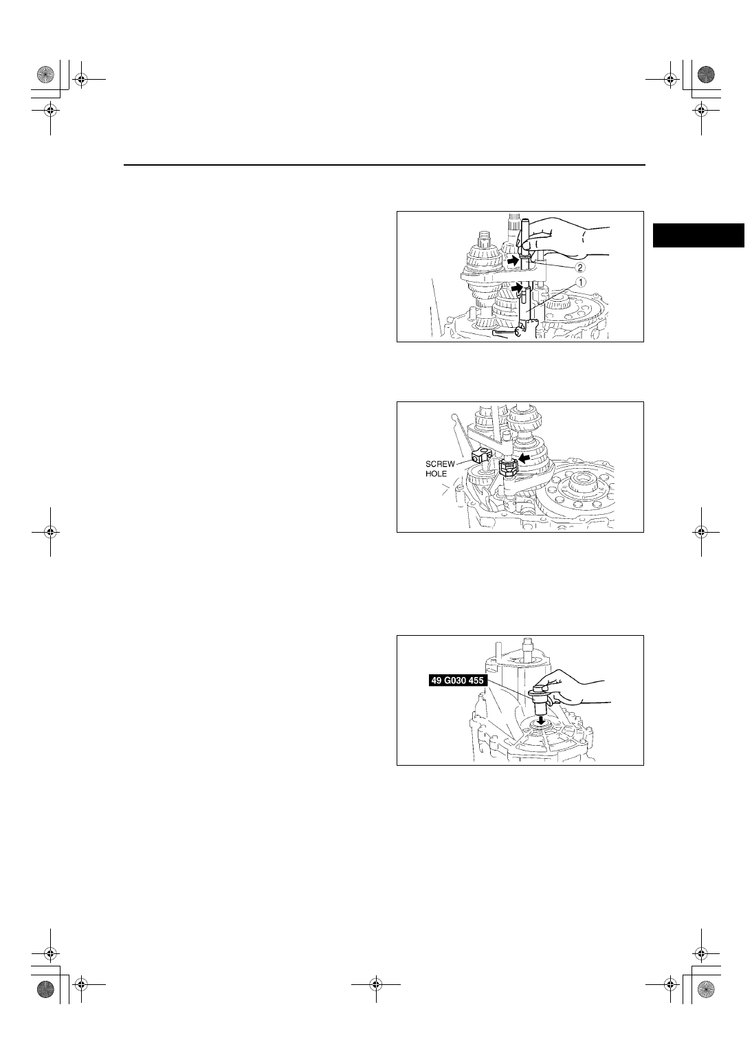
5th/Reverse Shift Rod End and 5th/Reverse Shift Rod Assembly Note

Note

The mark (indicated by the arrow in the 
figure) and the shift rod end mounting bolt 
hole must be aligned.

1. Install shift rod end 1 and the shift rod 2, and 

tighten the gate mounting bolt.

Tightening torque

11.8—13.7 N·m {120—140 kgf·cm,105—121 

in·lbf}

Reverse Idle Gear and Reverse Idle Shaft Assembly Note

1. Install the reverse idle gear and the reverse idler shaft.
2. Attach the magnet to the clutch housing.
3. Aligh the end of the interlock sleeve with the 

control lever (arrow), and at the same time, face 
the reverse idle shaft screw hole in the direction 
shown in the figure.

Transaxle Case Component Assembly Note

1. Apply a thin coat of sealant to the contact surfaces of the clutch housing and transaxle case, and tighten the 

transaxle case installation bolts to the specified torque.

Tightening torque

37.3—52.0 N·m {3.8—5.3 kgf·m, 28—38 ft·lbf}

2. Install the SSTs through the drive shaft and joint 

shaft hole.

Z4F5112M095

Z4F5112M096

Z4F5112M097

J–42

MANUAL TRANSAXLE 

Secondary 5th Gear Assembly Note

1. Install the secondary 5th gear as shown.

5th/Reverse Clutch Hub Component and 5th/Reverse Shift Fork Assembly Note

1. Install the 5th/reverse clutch hub component and 

the 5th/reverse shift fork together.

Locknut Assembly Note

1. Shift to 1st gear.
2. Lock the primary shaft using the SST.
3. Tighten new lock nuts onto the primary and 

secondary shafts.

Tightening torque

127.5—205.8 N·m {13.0—20.0 kgf·m, 95—144 

ft·lbf}

4. Stake the locknuts.

5. Measure the 5th gear thrust clearance using a 

dial indicator.

If not as specified, reassemble the transaxle.

Clearance

0.100—0.220 mm {0.0039—0.0087 in}

Maximum

0.270 mm {0.0106 in}

End Of Sie

A6E5112M098

A6E5112M099

A6E5112M100

A6E5112M101

TD–2

TECHNICAL DATA 

MANUAL TRANSAXLE

A6E931001029M01

TECHNICAL DATA

Item

Specification

Transaxle type

G35M-R

Thrust clearance

1st gear

Clearance

(mm {in})

0.05—0.28 {0.002—0.011}

Maximum

(mm {in})

0.33 {0.013}

2nd gear

Clearance

(mm {in})

0.18—0.46 {0.007—0.018}

Maximum

(mm {in})

0.51 {0.020}

3rd gear

Clearance

(mm {in})

0.05—0.20 {0.002—0.007}

Maximum

(mm {in})

0.25 {0.010}

4th gear

Clearance

(mm {in})

0.17—0.37 {0.007—0.014}

Maximum

(mm {in})

0.42 {0.017}

5th gear

Clearance

(mm {in})

0.100—0.220 {0.0040—0.0086}

Maximum

(mm {in})

0.270 {0.0106}

Oil clearance

1st gear

1st gear inner 
diameter

(mm {in})

39.500—39.525 {1.555—1.556}

Secondary 
shaft outer 
diameter

(mm {in})

39.445—39.470 {1.553—1.554}

Clearance

(mm {in})

0.030—0.080 {0.002—0.003}

2nd gear

2nd gear inner 
diameter

(mm {in})

35.015—35.035 {1.378—1.379}

Secondary 
shaft outer 
diameter

(mm {in})

34.945—34.905 {1.376—1.374}

Clearance

(mm {in})

0.05—0.09 {0.002—0.003}

3rd gear

3rd gear inner 
diameter

(mm {in})

36.000—36.025 {1.417—1.418}

Primary shaft 
outer 
diameter

(mm {in})

35.945—35.970 {1.415—1.416}

Clearance

(mm {in})

0.030—0.080 {0.001—0.003}

4th gear

4th gear inner 
diameter

(mm {in})

31.000—31.025 {1.220—1.221}

Primary shaft 
outer 
diameter

(mm {in})

30.945—30.970 {1.218—1.219}

Clearance

(mm {in})

0.030—0.080 {0.001—0.003}

5th gear

5th gear inner 
diameter

(mm {in})

34.000—34.025 {1.3386—1.3395}

Sleeve outer 
diameter

(mm {in})

33.945—33.970 {1.3365—1.3373}

Clearance

(mm {in})

0.030—0.080 {0.0012—0.0031}

Shift fork and hub 
sleeve

Clearance between 
1st/2nd shift fork and 
hub sleeve

Standard

(mm {in})

0.10—0.45 {0.004—0.017}

Maximum

(mm {in})

0.95 {0.037}

Clearance between 
3rd/4th shift fork and 
hub sleeve

Standard

(mm {in})

0.10—0.40 {0.004—0.015}

Maximum

(mm {in})

0.90 {0.035}

Clearance between 
5th shift fork and hub 
sleeve

Standard

(mm {in})

0.10—0.36 {0.004—0.014}

Maximum

(mm {in})

0.86 {0.034}

Synchronizer ring

Clearance between 
synchronizer ring and 
flank surface of gear

Standard

(mm {in})

1.50 {0.059}

Maximum

(mm {in})

0.80 {0.031}

Reverse idle gear and 
reverse lever

Clearance between 
reverse idle gear 
bushing and reverse 
lever

Standard

(mm {in})

0.10—0.35 {0.004—0.013}

maximum

(mm {in})

0.85 {0.033}


Content   ..  13  14  15