Mazda Transaxle G35M–R. Manual - part 14


  Index      Mazda     Mazda Transaxle G35M–R - service manual 2002 year


Search            


Content   ..  12  13  14  15   ..


Mazda Transaxle G35M–R. Manual - part 14


MANUAL TRANSAXLE 

J–37

J

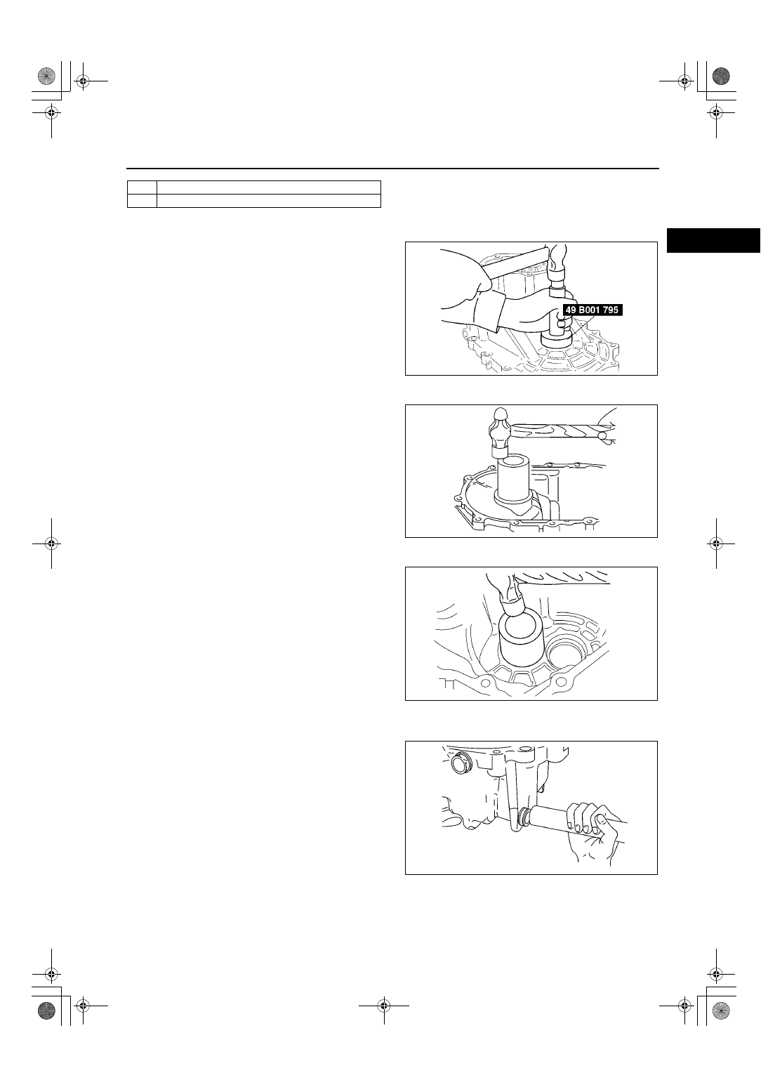
Oil Seal (Differential) Assembly Note

1. Apply transaxle oil to the new oil seal lip.
2. Install the oil seal using the SST.

Bearing Race (Differential) Assembly Note

1. Install the adjustment shim(s) and install the 

bearing race using a suitable pipe.

Bearing Race (Transaxle Case) Assembly Note

1. Install the adjustment shim(s) and install the 

bearing race using a suitable pipe.

Oil Seal (Change Rod Component) Assembly Note

1. Apply transaxle oil to the new oil seal lip.
2. Install the oil seal using a suitable pipe.

Outer diameter of pipe

26.0 mm {1.02 in}

32

O-ring

33

Crank lever shaft

Z4F5112M085

A6E5112M079

A6E5112M103

A6E5112M086

J–38

MANUAL TRANSAXLE 

Oil Seal (Primary Shaft)Assembly Note

1. Apply transaxle oil to outer circumference of the oil seal.
2. Install the new oil seal using a suitable pipe.

End Of Sie

5TH/REVERSE GEAR AND HOUSING PARTS ASSEMBLY

A6E511201029M06

1. Assemble in the order shown in the figure.

.

A6E5112M088

A6E5112M119

MANUAL TRANSAXLE 

J–39

J

Clutch Housing Assembly Note

1. Assemble the SST.
2. Assembly clutch housing on the SST.

1

Clutch housing
(See 

J–39 Clutch Housing Assembly Note

)

2

Control rod

3

Control end

4

1st/2nd shift fork

5

Control lever

6

Interlock lever

7

3rd/4th shift fork

8

Clutch hub

9

Clutch hub sleeve

10

Synchronizer key springs

11

Differential component

12

Secondary shaft gear component
(See 

J–40 Primary Shaft Gear Component and 

Secondary Shaft Gear Component Assembly Note

)

13

Primary shaft gear component
(See 

J–40 Primary Shaft Gear Component and 

Secondary Shaft Gear Component Assembly Note

)

14

Push pin

15

Shift fork and shift rod component
(See 

J–40 Shift Fork and Shift Rod Component 

Assembly Note

)

16

Crank lever component
(See 

J–40 Crank Lever Component and Crank 

Lever Shaft Assembly Note

)

17

Crank lever shaft
(See 

J–40 Crank Lever Component and Crank 

Lever Shaft Assembly Note

)

18

Pin

19

5th/reverse shift rod end
(See 

J–41 5th/Reverse Shift Rod End and 5th/

Reverse Shift Rod Assembly Note

)

20

5th/reverse shift rod
(See 

J–41 5th/Reverse Shift Rod End and 5th/

Reverse Shift Rod Assembly Note

)

21

Reverse idle gear
(See 

J–41 Reverse Idle Gear and Reverse Idle 

Shaft Assembly Note

)

22

Reverse idle shaft
(See 

J–41 Reverse Idle Gear and Reverse Idle 

Shaft Assembly Note

)

23

Magnet

24

Transaxle case component
(See 

J–41 Transaxle Case Component Assembly 

Note

)

25

Neutral switch

26

Back-up light switch

27

Lock bolt, ball and spring

28

Guide bolt

29

Lock bolt

30

Secondary 5th gear
(See 

J–42 Secondary 5th Gear Assembly Note

)

31

Gear sleeve

32

5th gear

33

5th synchronizer ring

34

5th/reverse clutch hub component
(See 

J–42 5th/Reverse Clutch Hub Component and 

5th/Reverse Shift Fork Assembly Note

)

35

5th/reverse shift fork
(See 

J–42 5th/Reverse Clutch Hub Component and 

5th/Reverse Shift Fork Assembly Note

)

36

Locknut (secondary shaft)
(See 

J–42 Locknut Assembly Note

)

37

Locknut (primary shaft)
(See 

J–42 Locknut Assembly Note

)

38

Rear cover

A6E5112M108

J–40

MANUAL TRANSAXLE 

Primary Shaft Gear Component and Secondary Shaft Gear Component Assembly Note

1. Install the primary shaft gear component and the secondary shaft gear component together.

Shift Fork and Shift Rod Component Assembly Note

1. Shift to 2nd gear and position the shift fork and 

shift rod component as shown.

2. Insert the spring seat and spring into the reverse 

lever shaft, install the steel ball, and place a 
scraper so that it contacts the steel ball.

3. With the edge of the control end against the 

scraper, when the control end is pushed in the 
direction of the arrow in the figure so that the ball 
goes into the shaft, the rod will at the same time 
line up with the shift rod coupling hole in the 
clutch housing.

4. Set each clutch hub sleeve to the neutral position, 

and tap the shift rod from above so that the steel 
ball goes into the center groove (of the three 
grooves in the control end).

5. Pull the ball part of the control end forward so that 

the steel ball goes into the detent in the groove.

Crank Lever Component and Crank Lever Shaft Assembly Note

1. Fit the crank lever between the change arm and the control end, and connect the crank lever shaft to the crank 

lever.

2. Aligh the pin holes of the crank lever shaft and the 

clutch housing, and insert a new pin.

A6E5112M091

Z4F5112M092

A6E5112M093

A6E5112M094


Content   ..  12  13  14  15   ..