Mazda Transaxle G35M–R. Manual - part 8


  Index      Mazda     Mazda Transaxle G35M–R - service manual 2002 year


Search            


Content   ..  6  7  8  9   ..


Mazda Transaxle G35M–R. Manual - part 8


MANUAL TRANSAXLE 

J–13

J

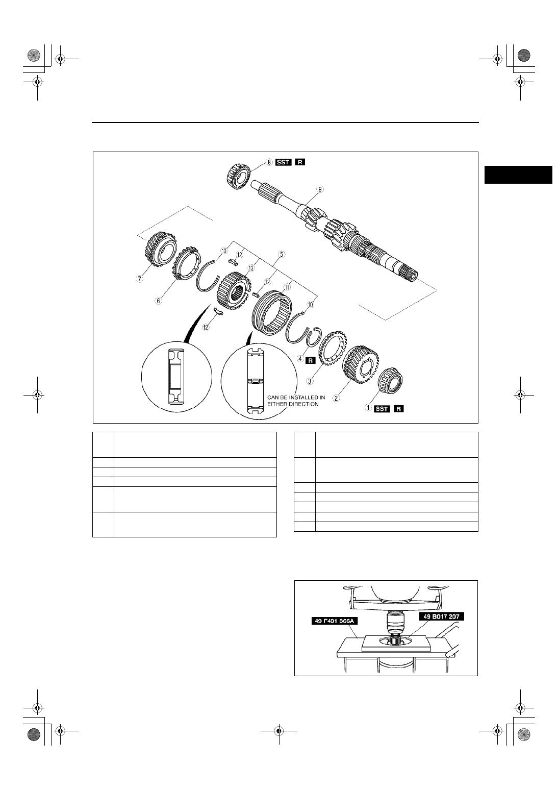
PRIMARY SHAFT COMPONENTS DISASSEMBLY

A6E511217201M02

1. Disassemble in the order shown in the figure.

.

Bearing (4th Gear End) Disassembly Note

1. Remove the bearing using the SST.

Z4F5112M023

1

Bearing (4th gear end)
(See 

J–13 Bearing (4th Gear End) Disassembly 

Note

)

2

4th gear

3

4th synchronizer ring

4

Retaining ring

5

3rd/4th clutch hub component
(See 

J–14 3rd/4th Clutch Hub Component, 3rd 

Synchronizer Ring and 3rd Gear Disassembly Note

)

6

3rd synchronizer ring
(See 

J–14 3rd/4th Clutch Hub Component, 3rd 

Synchronizer Ring and 3rd Gear Disassembly Note

)

7

3rd gear
(See 

J–14 3rd/4th Clutch Hub Component, 3rd 

Synchronizer Ring and 3rd Gear Disassembly Note

)

8

Bearing (primary shaft end)
(See 

J–14 Bearing (Primary Shaft End) 

Disassembly Note

)

9

Primary shaft gear

10

Synchronizer key springs

11

3rd/4th clutch hub sleeve

12

Synchronizer keys

13

3rd/4th clutch hub

Z4F5112M024

J–14

MANUAL TRANSAXLE 

3rd/4th Clutch Hub Component, 3rd Synchronizer Ring and 3rd Gear Disassembly Note

1. Remove the retaining ring.
2. Remove the 3rd/4th clutch hub component, 3rd 

synchronizer ring, and 3rd gear using the SST.

Bearing (Primary Shaft End) Disassembly Note

1. Remove the bearing using the SST.

Caution

••••

Use protective plates in the vise to 
prevent damage to the primary shaft 
gear.

End Of Sie

PRIMARY SHAFT COMPONENTS INSPECTION

A6E511217201M03

4th Gear, 3rd Gear Inspection

1. Inspect the synchronizer cones for wear.

If there is malfunction, replace parts as necessary.

2. Inspect the gear teeth for damage, wear, and cracks.

If there is malfunction, replace parts as necessary.

3. Inspect the synchronizer ring matching teeth for damage and wear.

If there is malfunction, replace the synchronizer ring.

4th Synchronizer Ring, 3rd Synchronizer Ring Inspection

1. Inspect the synchronizer ring teeth for damage, wear, and cracks.

If there is malfunction, replace parts as necessary.

2. Inspect the tapered surface for wear and cracks.

If there is malfunction, replace parts as necessary.

3. Measure the clearance between the synchronizer 

ring and the flank surface of the gear.

If not as specified, replace the synchronizer 
ring.

Note

Set the synchronizer ring squarely in the 
gear; then measure around the 
circumference.

Standard clearance

1.50 mm {0.059 in}

Minimum

0.80 mm {0.031 in}

Z4F5112M025

Z4F5112M026

A6E5112M027

MANUAL TRANSAXLE 

J–15

J

3rd/4th Clutch Hub Component Inspection

1. Inspect the clutch hub sleeve and hub operation.

If there is malfunction, replace parts as necessary.

2. Inspect the gear teeth for damage, wear, and cracks.

If there is malfunction, replace parts as necessary.

3. Inspect the synchronizer keys for damage, wear, and cracks.

If there is malfunction, replace parts as necessary.

4. Measure the clearance between the hub sleeve 

and shift forks.

If the clearance exceeds the maximum, 
replace the hub sleeve and shift fork as a set.

Standard

0.10—0.40 mm {0.004—0.015 in}

Maximum

0.90 mm {0.035 in}

Primary Shaft Gear Inspection

1. Inspect the gear contact surface for damage and wear.

If there is malfunction, replace the primary shaft.

2. Inspect the splines for damage and wear.

If there is malfunction, replace the primary shaft.

3. Inspect the gear teeth for damage, wear, and cracks.

If there is malfunction, replace the primary shaft.

4. Inspect the oil passage for clogging.

If there is malfunction, replace the primary shaft.

5. Measure the shaft gear runout.

If not as specified, replace the primary shaft.

Primary shaft runout

0.050 mm {0.0020 in} max.

6. Measure the clearance between the shaft gears 

and the gears.

If not as specified, replace parts as 
necessary.

End Of Sie

A6E5112M028

Gear

Shaft

(Outer dia.)

Gear

(Inner dia.)

Clearance

3rd

35.945—35.970 

{1.415—1.416}

36.000—36.025 

{1.417—1.418}

0.030—0.080 

{0.001—0.003}

4th

30.945—30.970 

{1.218—1.219}

31.000—31.025 

{1.220—1.221}

Z4F5112M029

Z4F5112M030

J–16

MANUAL TRANSAXLE 

PRIMARY SHAFT COMPONENTS ASSEMBLY

A6E511217201M04

1. Assemble in the order shown in the figure.

.

Z4F5112M031

1

3rd/4th clutch hub
(See 

J–17 3rd/4th Clutch Hub Assembly Note

)

2

Synchronizer keys

3

3rd/4th clutch hub sleeve

4

Synchronizer key springs

5

Primary shaft gear

6

Bearing (primary shaft end)
(See 

J–17 Bearing (Primary Shaft End) Assembly 

Note

)

7

3rd gear
(See 

J–17 3rd Gear, 3rd Synchronizer Ring, and 

3rd/4th Clutch Hub Component Assembly Note

)

8

3rd synchronizer ring
(See 

J–17 3rd Gear, 3rd Synchronizer Ring, and 

3rd/4th Clutch Hub Component Assembly Note

)

9

3rd/4th clutch hub component
(See 

J–17 3rd Gear, 3rd Synchronizer Ring, and 

3rd/4th Clutch Hub Component Assembly Note

)

10

Retaining ring

11

4th synchronizer ring
(See 

J–18 4th Synchronizer Ring, 4th Gear, and 

Bearing (4th Gear End) Assembly Note

)

12

4th gear
(See 

J–18 4th Synchronizer Ring, 4th Gear, and 

Bearing (4th Gear End) Assembly Note

)

13

Bearing (4th gear end)
(See 

J–18 4th Synchronizer Ring, 4th Gear, and 

Bearing (4th Gear End) Assembly Note

)


Content   ..  6  7  8  9   ..