Mazda Transaxle G35M–R. Manual - part 6


  Index      Mazda     Mazda Transaxle G35M–R - service manual 2002 year


Search            


Content   ..  4  5  6  7   ..


Mazda Transaxle G35M–R. Manual - part 6


MANUAL TRANSAXLE 

J–5

J

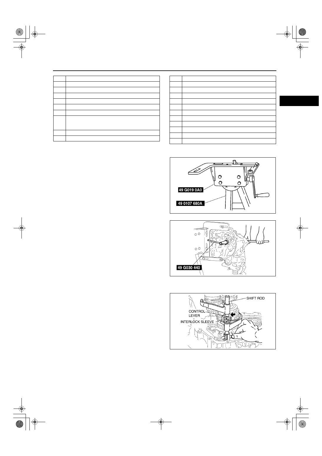
Locknut Disassembly Note

1. Assemble the SST.
2. Lift the transaxle and mount it on the SST.

3. Lock the primary shaft with the SST.
4. Shift to 1st gear to lock the rotation of the primary 

shaft.

5. Bend back the caulking of locknuts using a chisel.
6. Remove the locknuts from the primary and 

secondary shafts.

Shift Fork and Shift Rod Component Disassembly Note

1. Aligh the ends of the interlock sleeve and of the 

control lever (arrow). Turn the shift rod 
counterclockwise.

2. While holding the 1st/2nd shift fork with one hand 

and the 3rd/4th shift fork with the other, raise 
them both at the same time and shift each of the 
clutch hub sleeves.

17

Reverse idler shaft

18

Reverse idler gear

19

5th/reverse shift rod

20

5th/reverse shift rod end

21

Pin

22

Crank lever shaft

23

Crank lever component

24

Shift fork and shift rod component
(See 

J–5 Shift Fork and Shift Rod Component 

Disassembly Note

)

25

Push pin

26

Primary shaft gear component

27

Secondary shaft gear component

28

Differential component

29

Clutch housing

30

Synchronizer key springs

31

Clutch hub sleeve

32

Clutch hub

33

3rd/4th shift fork

34

Interlock sleeve

35

Control lever

36

1st/2nd shift fork

37

Control end

38

Control rod

A6E5112M108

Z4F5112M004

Z4F5112M005

J–6

MANUAL TRANSAXLE 

3. Lift the control end and remove the steel, and at 

the same time, remove the control rod from the 
clutch housing.

4. Separate the shift rod and shift fork component 

from each of the clutch hub sleeves.

End Of Sie

5TH/REVERSE GEAR AND HOUSING PARTS INSPECTION

A6E511201029M04

5th and Reverse Gear Inspection

1. Inspect the synchronizer cones for wear.

If there is malfunction, replace parts as necessary.

2. Inspect the gear teeth for damage, wear, and cracks.

If there is malfunction, replace parts as necessary.

3. Inspect the synchronizer ring matching teeth for damage and wear.

If there is malfunction, replace the synchronizer ring.

Synchronizer Ring Inspection

1. Inspect the synchronizer ring teeth for damage, wear, and cracks.

If there is malfunction, replace parts as necessary.

2. Inspect the tapered surface for wear and cracks.

If there is malfunction, replace parts as necessary.

3. Measure the clearance between the synchronizer 

ring and the flank surface of the gear.

If not as specified, replace the synchronizer 
ring.

Note

Set the synchronizer ring squarely in the 
gear; then measure around the 
circumference.

Standard clearance

1.50 mm {0.059 in}

Minimum

0.80 mm {0.031 in}

Clutch Hub Component Inspection

1. Inspect the clutch hub sleeve and hub operation.

If there is malfunction, replace parts as necessary.

2. Inspect the gear teeth for damage, wear, and cracks.

If there is malfunction, replace parts as necessary.

3. Inspect the synchronizer keys for damage, wear, and cracks.

If there is malfunction, replace parts as necessary.

4. Measure the clearance between the hub sleeve 

and shift fork.

If the clearance exceeds the maximum, 
replace the hub sleeve and shift fork as a set.

Standard clearance

0.10—0.36 mm {0.004—0.014 in}

Maximum clearance

0.86 mm {0.034 in}

A6E5112M006

A6E5112M118

A6E5112M008

MANUAL TRANSAXLE 

J–7

J

Reverse Idle Gear and Reverse Lever Inspection

1. Inspect the gear teeth for damage, wear, and cracks.

If there is malfunction, replace the reverse idle gear.

2. Measure the clearance between the reverse idle 

gear bushing and the reverse lever.

If not as specified, replace as necessary.

Standard clearance

0.10—0.35 mm {0.004—0.013 in}

Maximum Clearance

0.85 mm {0.033 in}

5th Gear and Sleeve Inspection

1. Measure the clearance between the 5th gear and 

the Sleeve.

If not as specified, replace parts as 
necessary.

5th gear inner diameter

34.000—34.025 mm {1.3386—1.3395 in}

Sleeve outer diameter

33.945—33.970 mm {1.3365—1.3373 in}

Clearance

0.030—0.080 mm {0.0012—0.0031 in}

End Of Sie

A6E5112M009

Z4F5112M010

J–8

MANUAL TRANSAXLE 

CLUTCH HOUSING AND TRANSAXLE CASE COMPONENTS DISASSEMBLY

A6E511217010M01

1. Disassemble in the order shown in the figure.

.

A6E5112M113

1

Bearing race (primary shaft)

2

Oil seal (primary shaft)
(See 

J–9 Oil Seal (Primary Shaft) Disassembly 

Note

)

3

Bearing race (secondary shaft)
(See 

J–9 Bearing Race (Secondary Shaft) 

Disassembly Note

)

4

Funnel

5

Guide plate component

6

Sealing cap

7

Roll pin
(See 

J–9 Roll Pin Disassembly Note

)

8

Control rod
(See 

J–9 Control Rod Disassembly Note

)

9

Selector 

10

Change arm

11

Bleather cover component

12

Bleather

13

Hole cover

14

Oil seal (differential)
(See 

J–10 Oil Seal (Differential) Disassembly Note

)

15

Bearing race (differential)
(See 

J–11 Bearing Race (Differential) Disassembly 

Note

)

16

Reverse lever shaft

17

Reverse lever

18

Drain plug and washer

19

Bearing race (transaxle case)
(See 

J–11 Bearing Race (Transaxle Case) 

Disassembly Note

)

20

Adjustment shim(s)

21

Bearing race (differential)
(See 

J–11 Bearing Race (Differential) Disassembly 

Note

)

22

Adjustment shim(s)

23

Oil seal (differential)
(See 

J–10 Oil Seal (Differential) Disassembly Note

)

24

Dowel pin

25

O-ring

26

Crank lever shaft

27

Clank component lever

28

Roll pin

29

Shift lever component

30

Key

31

Control end 

32

Spring and washer

33

shift lever shaft


Content   ..  4  5  6  7   ..