Mazda Transaxle G35M–R. Manual - part 4
ELECTRICAL SYSTEM
GI–11
GI
Replacement
•
Use the appropriate tools to remove a terminal as
shown. When installing a terminal, be sure to
insert it until it locks securely.
•
Insert a thin piece of metal from the terminal side
of the connector and with the terminal locking tab
pressed down, pull the terminal out from the
connector.
Sensors, Switches, and Relays
•
Handle sensors, switches, and relays carefully.
Do not drop them or strike them against other
objects.
Wiring Harness
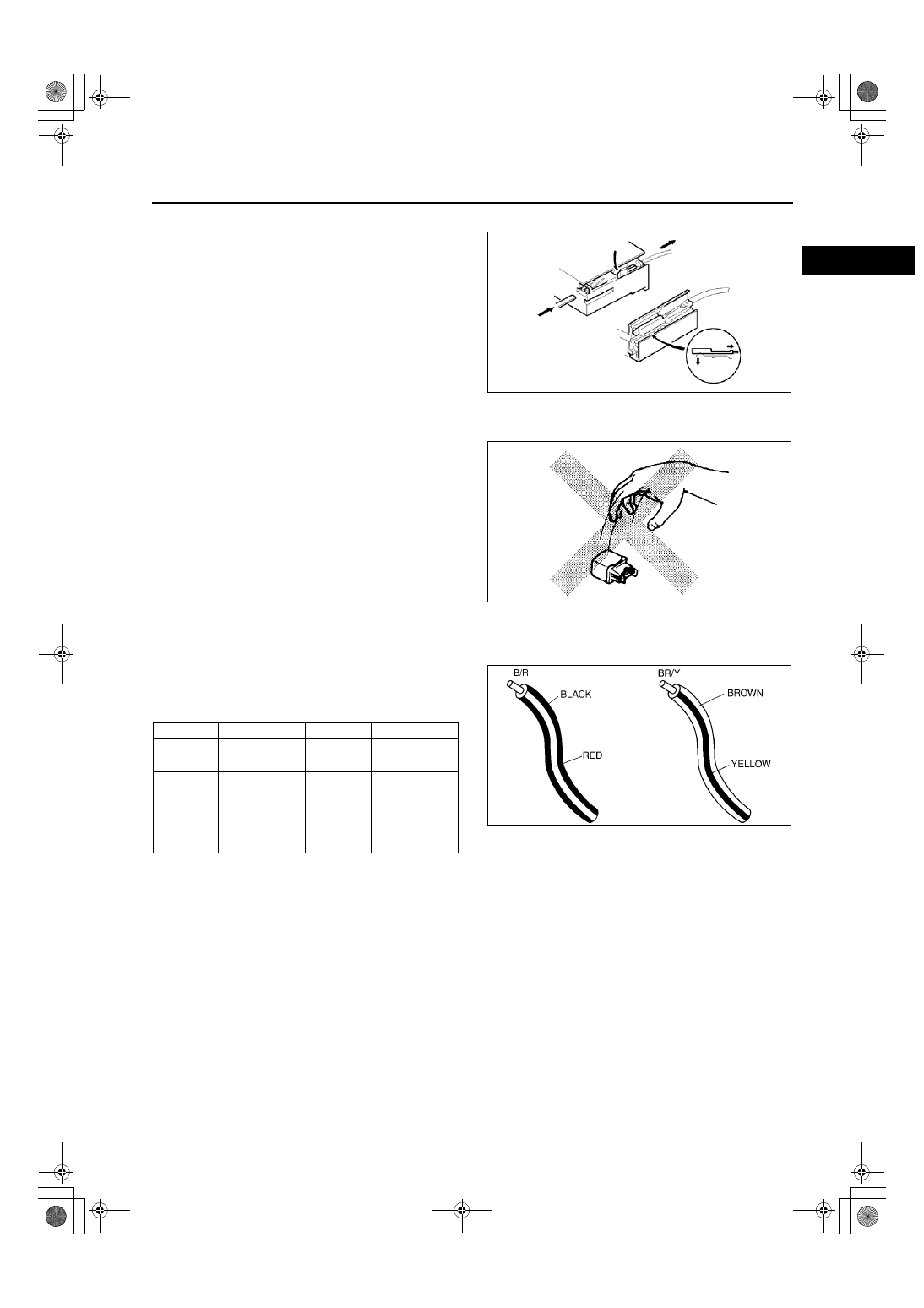
Wiring color codes
•
Two-color wires are indicated by a two-color code
symbol.
•
The first letter indicates the base color of the wire
and the second the color of the stripe.
End Of Sie
WGIWXX0046E
WGIWXX0047E
CODE
COLOR
CODE
COLOR
B
Black
O
Orange
BR
Brown
P
Pink
G
Green
R
Red
GY
Gray
V
Violet
L
Blue
W
White
LB
Light Blue
Y
Yellow
LG
Light Green
X3U000WB7