Mazda Automatic Transaxle JA5A-EL. Manual - part 29


  Index      Mazda     Mazda Automatic Transaxle JA5A-EL - service manual 2002 year


Search            


Content   ..  27  28  29  30   ..


Mazda Automatic Transaxle JA5A-EL. Manual - part 29


AUTOMATIC TRANSAXLE 

K1–21

K1

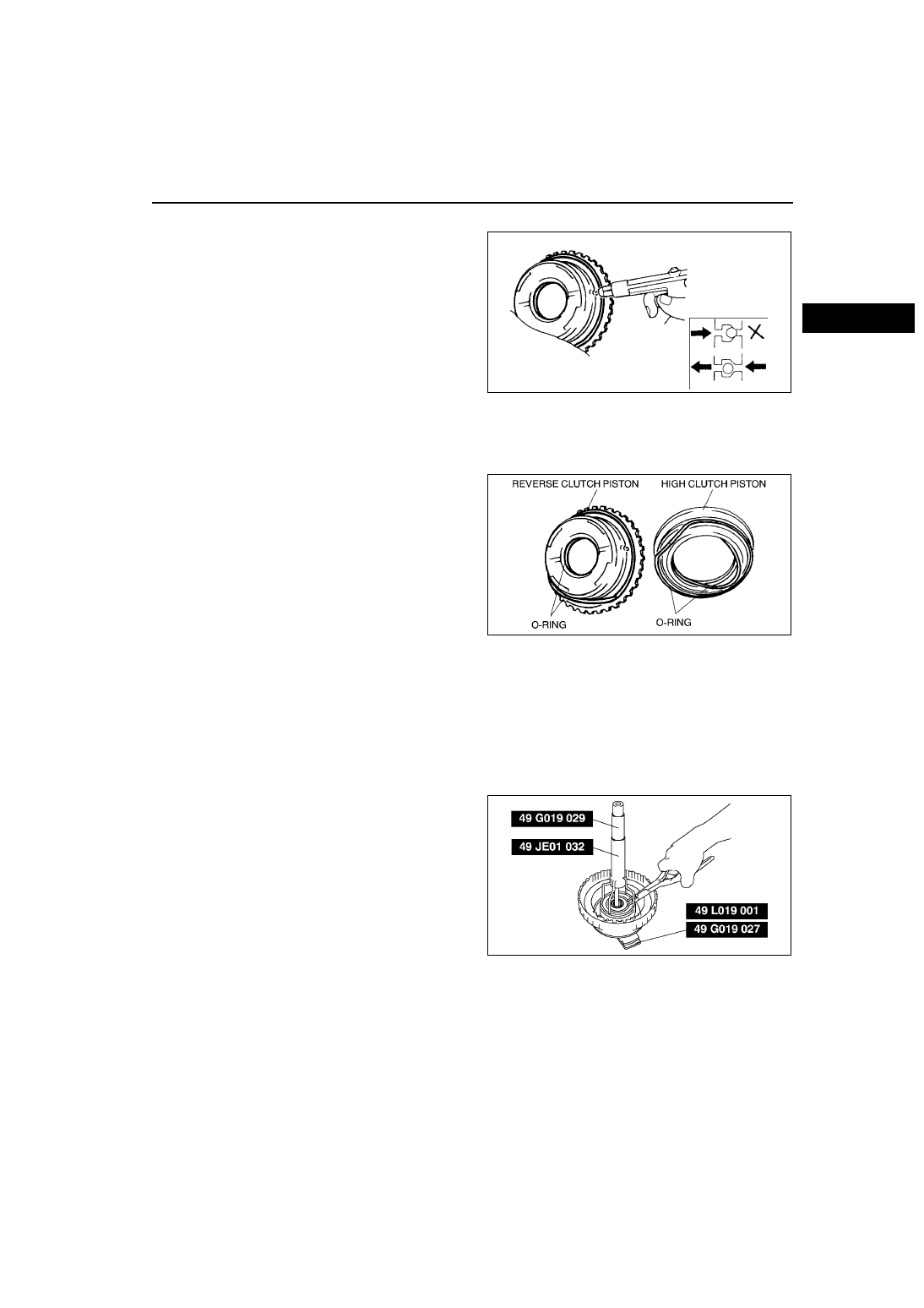
1. Verify that there is no air leakage when applying compressed air through the oil hole opposite the return spring.

2. Verify that there is airflow when applying 

compressed air through the oil hole on the return 

spring side.

• Replace the coasting clutch piston if it is 

damaged or malfunctioning.

Air pressure

390 kPa {4.0 kgf/cm

2

, 57 psi} max.

End Of Sie

REVERSE CLUTCH AND HIGH CLUTCH ASSEMBLY

AME571419500A04

Assembly Procedure

1. Apply a coat of ATF to new O-rings, then install 

them to reverse and high clutch pistons.

2. Apply a coat of ATF to inside of reverse clutch 

piston, then install the high clutch piston into the 

reverse clutch piston while rotating the piston by 

hand.

3. Apply a coat of ATF to inside of drum, then install 

the reverse clutch piston into drum while rotating 

the piston by hand.

Note

• After installing required parts to the piston, 

ensure that the piston rotates smoothly by 

hand. If not, the O-ring may be caught.

4. Install the return spring.

5. Install the spring retainer as follows.

(1) Position the spring retainer.

Caution

•••• Depress the spring retainer only enough to remove the snap ring. Overpressing will damage the 

retainer component edges.

(2) Install the SSTs in clutch drum as shown.

(3) Install the snap ring.

(4) Remove the SSTs.

Caution

•••• Depress the spring retainer only enough 

to install the snap ring. Overpressing will 

damage the retainer component edges.

AMU0517A144

AMU0517A058

AMU0517A165

K1–22

AUTOMATIC TRANSAXLE 

6. Install the plates and driven plates in the order as 

shown in the figure.

7. Install the retaining plate.

8. Install the snap ring.

End Of Sie

LOW CLUTCH PREINSPECTION

AME571419500A05

Clutch Operation

1. Set the low clutch onto the transaxle case.

Warning

•••• Using compressed air can cause dirt and other particles to fly out, causing injury to the eyes. 

Wear protective eye wear whenever using compressed air.

Caution

•••• Applying compressed air to the assembled clutch pack for longer than 3 seconds at a time will 

damage the seal. Do not apply compressed air for more than the aforementioned time when 

testing the system.

Note

• Regarding the position of the hole into which air is blown, refer to item “Oil pressure circuit” in this manual.

AMU0517A060

AMU0517A061

AUTOMATIC TRANSAXLE 

K1–23

K1

2. Inspect the clutch operation by applying 

compressed air through the fluid passages 

shown.

• If not as specified, replace parts where 

necessary. 

Air pressure

390 kPa {4.0 kgf/cm

2

, 57 psi} max.

Clutch Clearance

1. Using a thickness gauge, measure clearance 

between the retaining plate and the snap ring.

• If not as specified, replace parts where 

necessary. 

• If the specified clearance is exceeded, 

replace all clutch plates with new ones. And 

then, select a suitable retaining plate so that 

the specified clearance is obtained. 

Clearance:

1.1—1.3 mm {0.044—0.051 in}

Retaining plate thickness

mm {in}

End Of Sie

AMU0517A073

3.8 {0.150}

3.9 {0.154}

4.0 {0.157}

4.1 {0.161}

4.2 {0.165}

4.3 {0.169}

4.4 {0.173}

4.5 {0.177}

4.6 {0.181}

AMU0517A074

K1–24

AUTOMATIC TRANSAXLE 

LOW CLUTCH DISASSEMBLY

AME571419500A06

Snap Ring Disassembly Note

Caution

•••• Depress the spring retainer only enough to remove the snap ring. Overpressing will damage the 

retainer component edges.

AMU0517A066

1

Snap ring

2

Retaining plate

3

Drive plate

4

Driven plate

5

Dished plate

6

Snap ring

(See 

K1–24 Snap Ring Disassembly Note

)

7

O-ring

8

Cancel force cover

9

Return spring

10 Piston

(See 

K1–25 Clutch Piston Disassembly Note

)

11 O-ring
12 Seal ring
13 Clutch drum


Content   ..  27  28  29  30   ..