Mazda Automatic Transaxle JA5A-EL. Manual - part 27


  Index      Mazda     Mazda Automatic Transaxle JA5A-EL - service manual 2002 year


Search            


Content   ..  25  26  27  28   ..


Mazda Automatic Transaxle JA5A-EL. Manual - part 27


AUTOMATIC TRANSAXLE 

K1–13

K1

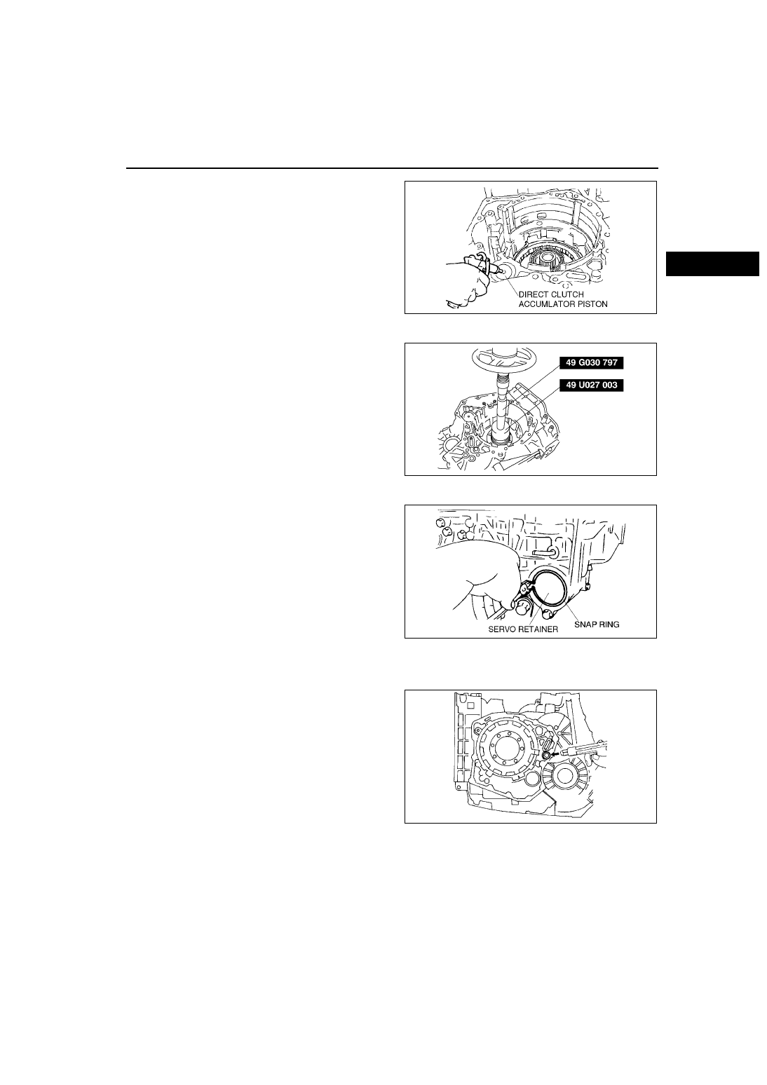
(2) Remove the direct clutch accumulator piston 

by applying compressed air through the hole 

of the direct clutch accumulator piston.

(3) Remove the springs.

62. Remove the output gear.

(1) Remove the installation bolts of output gear.

(2) Set the SSTs to the output gear, and remove 

the output gear using a press.

63. Remove the brake band servo.

(1) Remove the snap ring.

Warning

•••• Using compressed air can cause dirt and 

other particles to fly out, causing injury 

to the eyes. Wear protective eye wear 

whenever using compressed air.

Caution

•••• Applying compressed air to the 

assembled clutch pack for longer than 3 

seconds at a time will damage the seal. 

Do not apply compressed air for more 

than the aforementioned time when 

testing the system.

(2) Remove the servo retainer and reduction 

accumulator piston component by applying 

compressed air as shown.

AMU0517A146

AMU0517A177

AMU0517A018

AMU0517A147

K1–14

AUTOMATIC TRANSAXLE 

(3) Pushing the piston stem using a wood stick, 

remove the snap ring.

(4) Remove the spacer, band servo piston, and 

spring.

64. Remove the oil pipe from the converter housing.

65. Remove the baffle plate.

66. Set the SST to the reduction gear bearing outer 

race, and remove it.

End Of Sie

TORQUE CONVERTER INSPECTION

AME571419100A01

1. Inspect the outer surface of the torque converter for damage or cracks, and replace it if necessary.

2. Inspect for rust and damage on the pilot hub of the torque converter or on the boss.

• If there is any, remove the rust completely.

End Of Sie

OIL PUMP DISASSEMBLY

AME571419220A01

1. Disassemble in the order indicated in the table.

AMU0517A160

AMU0517A133

AMU0517A125

AMU0517A187

AUTOMATIC TRANSAXLE 

K1–15

K1

Oil Pump Cover Disassembly Note

1. Remove mounting bolts evenly in the pattern 

shown and remove the oil pump cover from the oil 

pump housing.

Inner Rotor, Outer Rotor Disassembly Note

1. Mark the outer and inner rotors without scratching 

or denting them, then remove them from the oil 

pump housing.

End Of Sie

1

O-ring

2

Bolt

3

Oil pump housing

4

Inner rotor

(See 

K1–15 Inner Rotor, Outer Rotor Disassembly 

Note

)

5

Outer rotor

(See 

K1–15 Inner Rotor, Outer Rotor Disassembly 

Note

)

6

Oil pump cover

(See 

K1–15 Oil Pump Cover Disassembly Note

)

7

Seal ring

8

Oil seal

AME5714A002

AMU0517A048

AMU0517A143

K1–16

AUTOMATIC TRANSAXLE 

OIL PUMP INSPECTION

AME571419220A02

1. Check frictional surfaces of the inner rotor, outer rotor, and oil pump housing for damage or abnormal wear.

2. Check bushings for damage or abnormal wear.

3. Check other parts for external.

4. Measure the inner diameter of the oil pump 

housing A.

Specification A

Maximum: 42.045 mm {1.6553 in}

• If not as specified, replace the oil pump 

housing.

5. Measure the rotor side clearances.

(1) Install outer and inner rotors to the oil pump 

housing.

(2) Using straightedge and thickness gauge, 

measure height difference (side clearance) 

between the oil pump end surface and the 

rotor upper surface.

Clearance

Outer rotor: 0.02—0.04 mm 

{0.0008—0.0015 in}

Inner rotor: 0.02—0.05 mm 

{0.0008—0.0019 in}

• If not as specified, replace the oil pump.

6. Using thickness gauge, measure the clearance 

between the outer rotor and the inner rotor.

Oil clearance

Standard: 0.02—0.15 mm 

{0.0008—0.0059 in}

• If not as specified, replace the oil pump 

component where necessary.

End Of Sie

OIL PUMP ASSEMBLY

AME571419220A03

Assembly Procedure

1. Install the new oil seal to the oil pump housing 

using the SSTs.

2. Apply ATF to the outer and inner rotors.

AMU0517A188

AMU0517A049

AMU0517A050

AMU0517A168


Content   ..  25  26  27  28   ..