Mazda Automatic Transaxle JA5A-EL. Manual - part 13


  Index      Mazda     Mazda Automatic Transaxle JA5A-EL - service manual 2002 year


Search            


Content   ..  11  12  13  14   ..


Mazda Automatic Transaxle JA5A-EL. Manual - part 13


AUTOMATIC TRANSAXLE 

K–33

K

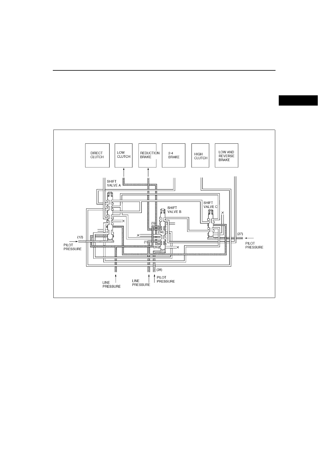
Shift Valve A, B, and C

Outline

• Shift valves A, B, and C switch the oil passages. These valves switch the line pressure oil passage according 

to each shift solenoid operation and apply operation pressure (line pressure) to each clutch and brake.

Operation

First gear (engine brake operation not possible)

• Each shift solenoid is set to first gear (engine brake operation not possible) mode. The pilot pressure is applied 

to the bottom end of every shift valve and each shift valve is positioned on the upper side. Line pressure (1) is 

applied to the low clutch passing through shift valve B (oil passage (35)). Line pressure (5) is not applied to the 

reduction brake passing through shift valve B (oil passage (34)).

AMU0517A541

K–34

AUTOMATIC TRANSAXLE 

Second gear

• Each shift solenoid is set to second gear mode. Pilot pressure is applied to the bottom end of shift valves A, B, 

and shift valves A, B are positioned on the upper side. Conversely, shift valve C is positioned on the down side 

by spring force. Line pressure (1) flows through shift valve B and is applied to the low clutch (oil passage (35)). 

Also, line pressure (1) flows through shift valve C and is applied to 2-4 brake acting through shift valve A (oil 

passage (37)). Line pressure (5) is not applied to the reduction brake flowing through shift valve B (oil passage 

(34)).

AMU0517A542

AUTOMATIC TRANSAXLE 

K–35

K

Third gear

• Each shift solenoid is set to third gear mode. Pilot pressure is applied to the bottom end of shift valve B and 

shift valve B is positioned on the upper side. Conversely, shift valves A and C is positioned on the down side by 

spring force. Line pressure (1) flows through shift valve B and is applied to the low clutch (oil passage (35)). 

Also, line pressure (1) flows through the shift valve C and acts through the shift valve A and is applied to the 

high clutch (oil passage (23)). Line pressure (5) flows through shift valve B and is not applied to the reduction 

brake (oil passage (34)).

AMU0517A543

K–36

AUTOMATIC TRANSAXLE 

Forth gear

• Each shift solenoid is set to forth gear mode. Pilot pressure is applied to the bottom end of shift valve C and 

positioned on the upper side. Conversely, shift valve A and B is positioned on the down side by spring force. 

Line pressure (1) flows through shift valve B and acts through the shift valve A and is applied the 2-4 brake (oil 

passage (37)). Conversely, line pressure (32) flows through shift valve C and acts through the shift valve A and 

is applied to the high clutch (oil passage (23)). Line pressure (5) flows through shift valve A and acts through 

shift valve B and is not applied to the reduction brake (oil passage (38)).

AMU0517A544


Content   ..  11  12  13  14   ..