Mazda RX-8. Manual - part 4
 

  Index      Mazda     Mazda RX-8 - service repair manual 2004-2006 year


Search            


Content   ..  1  2  3  4  5  ..


Mazda RX-8. Manual - part 4


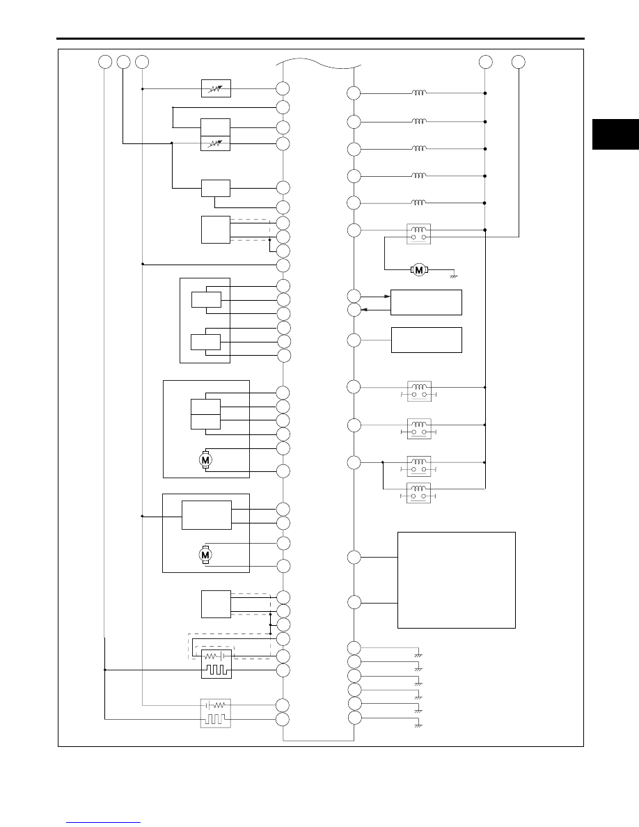
ON-BOARD DIAGNOSTIC 

01–02–3

01–02

End Of Sie

PCM

5U

5K

5N

5S

4K

1T

1F

1G

1J

2F

1M

5Z

1W

1L

2P

1O

2I

2T

5W

5AA

5X

5AD

2K

a

b

ECT SENSOR

IAT SENSOR

MAF SENSOR

BARO SENSOR

KS

APP SENSOR

TP SENSOR

THROTTLE ACTUATOR

APV
POSITION
SENSOR

APV MOTOR

ECCENTRIC SHAFT POSITION SENSOR

FRONT HO2S

REAR HO2S

VFAD SOLENOID VALVE *

1

VDI SOLENOID VALVE

SSV SOLENOID VALVE

PURGE SOLENOID VALVE

AIR SOLENOID VALVE

AIR PUMP RELAY

AIR PUMP

GENERATOR

A/C AMPLIFIER

A/C RELAY

COOLING FAN RELAY NO.1

COOLING FAN RELAY NO.2

COOLING FAN RELAY NO.3

OTHER MODULE
·EPS CONTROL MODULE
·TCM
·ABS HU/CM
·DSC HU/CM
·KEYLESS CONTROL MODULE
·TPMS CONTROL MODULE
·STEERING ANGLE SENSOR
·INSTRUMENT CLUSTER

4X

5C

5AB

4Y

5F

5AE

1Q

1C

1B

2X

2H

2B

3J

3G

3B

1S

2U

2C

1V

2Q

2A

4O

5O

5R

5T

4A

4J

5D

4V

4S

1U

APV MOTOR *

1

THROTTLE BODY

*

1

: 13B-MSP (HIGH POWER)

CAN_H

CAN_L

NO.1

NO.2

NO.1

NO.2

c

c

d

EHU140ZT8004

ON-BOARD DIAGNOSTIC 

01–02–4

DIAGNOSTIC TEST MODE

EHU010200000102

•

The diagnostic test mode is essentially carried over from that of the 2005 MY except for following.

—

To meet OBD-II regulations, modes 02, 03, and 06 have been changed.

On-board system readiness test

•

The items supported by the on-board system readiness test are shown below.
Continuous monitoring system

—

HO2S heater

—

Thermostat

—

Fuel system

—

Misfire

—

CCM

Intermittent monitoring system

—

HO2S

—

AIR system

—

Catalyst

—

EVAP system

—

Engine cooling system

—

CSERS

OBD-II Freeze Frame Data (Mode 02)

•

Differences between the 2006 MY and 2005 MY Freeze Frame Data monitor items are shown below.

Freeze Frame Data monitor table

X: Applicable

—: Not applicable

Diagnostic test mode

Item

Mode 01

Sending diagnostic data (PID data monitor/On-board system readiness test)

Mode 02

Sending freeze frame data

Mode 03

Sending emission-related malfunction code (DTC)

Mode 04

Clearing/resetting emission-related malfunction information

Mode 06

Sending intermittent monitoring system test results (DMTR)

Mode 07

Sending continuous monitoring system test results (pending code)

Mode 08

On-board device control (simulation test, active command mode)

Mode 09

Request vehicle information

2006 MY

2005 MY

Full names

Unit

X

X

DTC that caused required Freeze Frame Data storage

—

X

X

Fuel system status

Refer to list below.

X

X

Calculated LOAD Value

%

X

X

Engine Coolant Temperature

°

C

°

F

X

X

Short term fuel trim

%

X

X

Long term fuel trim

%

X

X

Engine RPM

rpm

X

X

Vehicle Speed Sensor

km/h

mph

X

X

Ignition Timing Advance

°

X

X

Intake Air Temperature

°

C

°

F

X

X

Air Flow Rate from Mass Air Flow Sensor 

g/s

X

X

Absolute  Throttle Position

%

X

X

Commanded Secondary Air Status

—

X

—

Rear HO2S

%

X

X

Time since engine start

s

X

X

Commanded Evaporative Purge

%

X

X

Fuel Level Input

%

X

X

Number of warm-ups since DTCs cleared

—

X

X

Distance travelled since DTCs cleared

km

miles

X

X

Barometric Pressure

kPa

X

X

Catalyst Temperature

°

C

°

F

X

X

Control module voltage

V

X

X

Absolute load value

%

ON-BOARD DIAGNOSTIC 

01–02–5

01–02

Meaning of fuel system loop status

•

The following information is displayed on the tester.

—

Feedback operating: HO2S being used for feedback is normal.

—

Feedback stops: ECT is lower than the determined feedback zone.

—

Feedback stops: Open loop due to driving condition.

—

Feedback stops: Open loop due to detected system fault.

OBD-II Diagnostic Trouble Code (Mode 03)

•

The following DTCs have been adopted.

—

P0116, P0134, P0137, P0411, P050A

•

Differences between the 2006 MY and 2005 MY DTCs are shown below.

DTC table

×

: Applicable

—: Not applicable

X

X

Commanded Equivalence Ratio

—

X

X

Relative Throttle Position

%

X

X

Ambient air temperature

°

C

X

X

Absolute Throttle Position No.2

%

X

X

Accelerator Pedal Position No.3

%

X

X

Accelerator Pedal Position No.4

%

X

X

Commanded Throttle Actuator Control

%

2006 MY

2005 MY

Full names

Unit

DTC No.

Condition

MIL

DC

Monitor 

item

*1

Self -test 

type

*4

Memory 

function

2006 MY 2005 MY

P0030

←

Front HO2S heater control circuit problem

ON

2

HO2S heater

C, O, R

×

P0031

←

Front HO2S heater control circuit low

ON

2

HO2S heater

C, O, R

×

P0032

←

Front HO2S heater control circuit high

ON

2

HO2S heater

C, O, R

×

P0037

←

Rear HO2S heater control circuit low

ON

2

HO2S heater

C, O, R

×

P0038

←

Rear HO2S heater control circuit high

ON

2

HO2S heater

C, O, R

×

P0076

←

VDI solenoid valve control circuit low

OFF

2

Other

C, O, R

×

P0077

←

VDI solenoid valve control circuit high

OFF

2

Other

C, O, R

×

P0101

←

MAF sensor circuit range/performance problem

ON

2

CCM

C

×

P0102

←

MAF sensor circuit low input

ON

1

CCM

C, O, R

×

P0103

←

MAF sensor circuit high input

ON

1

CCM

C, O, R

×

P0107

←

BARO sensor circuit low input

ON

1

CCM

C, O, R

×

P0108

←

BARO sensor circuit high input

ON

1

CCM

C, O, R

×

P0111

←

IAT sensor circuit range/performance problem

ON

2

CCM

C

×

P0112

←

IAT sensor circuit low input

ON

1

CCM

C, O, R

×

P0113

←

IAT sensor circuit high input

ON

1

CCM

C, O, R

×

P0116

*3

—

Engine coolant temperature circuit range/
performance

ON

2

Engine 
cooling 
system

C

×

P0117

←

ECT sensor circuit low input

ON

1

CCM

C, O, R

×

P0118

←

ECT sensor circuit high input

ON

1

CCM

C, O, R

×

P0122

←

TP sensor No.1 circuit low input

ON

1

CCM

C, O, R

×

P0123

←

TP sensor No.1 circuit high input

ON

1

CCM

C, O, R

×

P0125

←

Insufficient coolant temperature for closed loop fuel 
control

ON

2

Engine 
cooling 
system

C

×

P0126

←

Insufficient coolant temperature for stable operation

ON

2

Thermostat

C

×

P0130

←

Front HO2S circuit problem

ON

2

HO2S

C, O, R

×

P0131

←

Front HO2S circuit low voltage

ON

2

HO2S

C, O, R

×

P0132

←

Front HO2S circuit high voltage

ON

2

HO2S

C, O, R

×

P0133

←

Front HO2S circuit slow response

ON

2

HO2S

C

×

P0134

*3

—

Front HO2S no activity detected

ON

2

HO2S

C, R

×

P0137

*3

—

Rear HO2S circuit low input

ON

2

HO2S

C

×

P0138

←

Rear HO2S circuit high voltage

ON

2

HO2S

C, R

×

ON-BOARD DIAGNOSTIC 

01–02–6

P0139

←

Rear HO2S circuit slow response

ON

2

HO2S

C, R

×

P0171

←

System too lean

ON

2

Fuel system

C, R

×

P0172

←

System too rich

ON

2

Fuel system

C, R

×

P0222

←

TP sensor No.2 circuit low input

ON

1

CCM

C, O, R

×

P0223

←

TP sensor No.2 circuit high input

ON

1

CCM

C, O, R

×

P0300

←

Random misfire detected

Flas

h/ON

1 or 

2

Misfire

C

×

P0301

←

Front rotor misfire detected

Flas

h/ON

1 or 

2

Misfire

C

×

P0302

←

Rear rotor misfire detected

Flas

h/ON

1 or 

2

Misfire

C

×

P0327

←

KS circuit low input

ON

1

CCM

C, O, R

×

P0328

←

KS circuit high input

ON

1

CCM

C, O, R

×

P0335

←

Eccentric shaft position sensor circuit problem

ON

1

CCM

C

×

P0336

←

Eccentric shaft position sensor circuit range/
performance problem

ON

1

CCM

C, R

×

P0410

←

Secondary air injection system problem

ON

2

AIR system

C, R

×

P0411

*3

—

Secondary air injection system incorrect upstream 
flow

ON

2

AIR system

C

×

P0420

←

Catalyst system efficiency below threshold

ON

2

Catalyst

C

×

P0441

←

EVAP system incorrect purge flow

ON

2

EVAP system

C, R

×

P0442

←

EVAP system leak detected (small leak)

ON

2

EVAP system

C, R

×

P0443

←

Purge solenoid valve circuit problem

ON

2

CCM

C, R

×

P0446

←

EVAP system vent control circuit problem

ON

2

EVAP system

C, R

×

P0455

←

EVAP system leak detected (large leak)

ON

2

EVAP system

C, R

×

P0456

*2

←

EVAP system leak detected (very small leak)

ON

2

EVAP system

C, R

×

P0461

←

Fuel gauge sender unit circuit range/performance 
problem

ON

2

CCM

C

×

P0462

←

Fuel gauge sender unit (main) circuit low input

ON

2

CCM

C, O, R

×

P0463

←

Fuel gauge sender unit (main) circuit high input

ON

2

CCM

C, O, R

×

P0480

←

Cooling fan No.1 control circuit problem

OFF

2

Other

C, O, R

×

P0481

←

Cooling fan No.2 control circuit problem

OFF

2

Other

C, O, R

×

P0500

←

VSS circuit problem

ON

2

CCM

C

×

P0505

←

Idle air control system problem

OFF

—

—

R

—

P0506

←

Idle air control system RPM lower than expected

ON

2

CCM

C

×

P0507

←

Idle air control system RPM higher than expected

ON

2

CCM

C

×

P050A

*3

—

Cold start idle air control system performance

ON

2

CSERS

C

×

P0562

←

System voltage low (KAM)

ON

1

CCM

C, O, R

×

P0564

←

Cruise control switch input circuit problem

OFF

1

Other

C, O, R

×

P0571

←

Brake switch input circuit problem

OFF

1

Other

C, O, R

×

P0601

←

PCM memory check sum error

ON

1

CCM

C, O, R

×

P0602

←

PCM programming error

ON

1

CCM

C, O, R

×

P0604

←

PCM random access memory error

ON

1

CCM

C, O, R

×

P0610

←

PCM vehicle options error

ON

1

CCM

C, O, R

×

P0638

←

Throttle actuator control circuit range/performance 
problem

ON

1

CCM

C

×

P0661

←

SSV solenoid valve control circuit low

ON

2

CCM

C, O, R

×

P0662

←

SSV solenoid valve control circuit high

ON

2

CCM

C, O, R

×

P0703

←

Brake switch input circuit problem

ON

2

CCM

C

×

P0704

*3

←

CPP switch input circuit problem

ON

2

CCM

C

×

P0850

*3

←

Neutral switch input circuit problem

ON

2

CCM

C

×

P1260

←

Immobilizer system problem

OFF

1

Other

C, O

—

P1686

←

Metering oil pump control circuit low flow side 
problem

ON

1

CCM

C, R

×

DTC No.

Condition

MIL

DC

Monitor 

item

*1

Self -test 

type

*4

Memory 

function

2006 MY 2005 MY


Content   ..  1  2  3  4  5  ..