Mazda CX 7. Manual - part 431


  Index      Mazda     Mazda CX 7 - service repair manual 2007 year


Search            


Content   ..  429  430  431  432   ..


Mazda CX 7. Manual - part 431


ENTERTAINMENT 

09-20–15

09-20

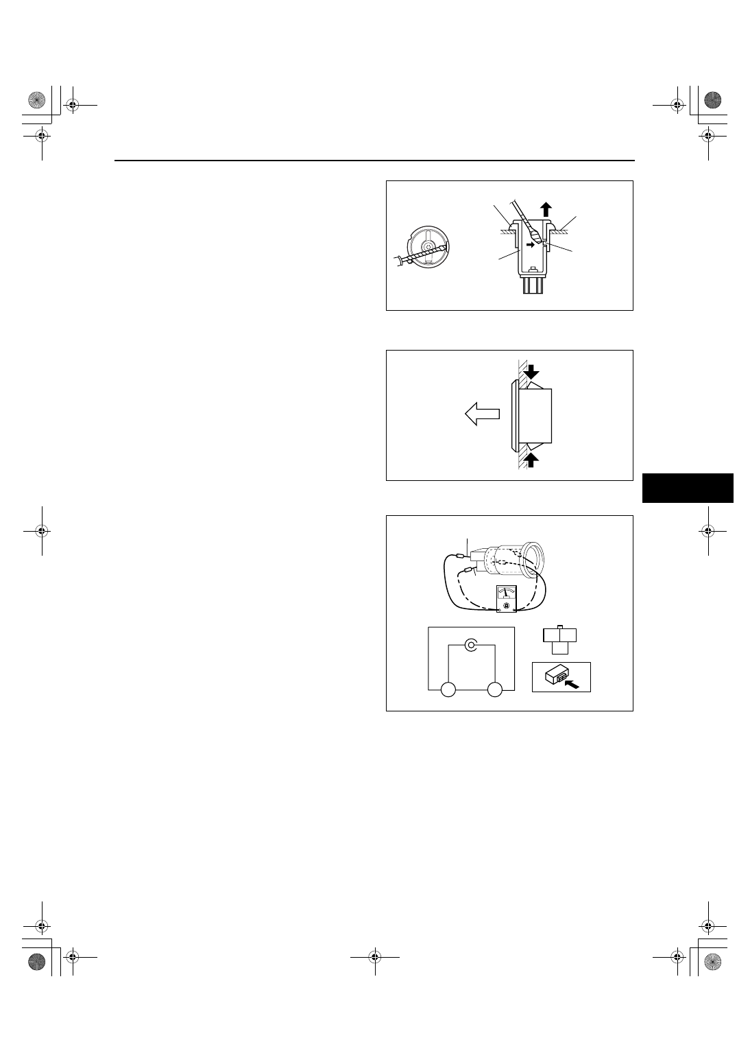
Accessory Socket Removal Note

1. While pressing a tape-wrapped flathead 

screwdriver against the cap projection, pull the 
accessory socket outward.

Cap Removal Note

1. While pressing the tabs, pull the cap outwards.

End Of Sie

ACCESSORY SOCKET INSPECTION

id092000800500

1. Connect a tester as shown in the figure and verify 

that there is continuity.

• If the continuity cannot be verified, replace the 

accessory socket.

End Of Sie

ACCESORY 
SOCKET

CAP

PROJECTION

HOLE COVER

acxuuw00001015

TAB

TAB

acxuuw00001016

C

B

*

B

C

TERMINAL B

TERMINAL C

B6U0920W005

1871-1U-06B(09-20).fm  15 ページ  2006年3月15日 水曜日 午後12時49分

POWER SYSTEMS 

09-21–1

09-21

09-21

POWER SYSTEMS

POWER SYSTEM LOCATION INDEX  . .  09-21–1
FUSE SERVICE CAUTIONS . . . . . . . . . .  09-21–1
IGNITION SWITCH 

REMOVAL/INSTALLATION. . . . . . . . . .  09-21–2

IGNITION SWITCH INSPECTION . . . . . .  09-21–2
KEY REMINDER SWITCH 

REMOVAL/INSTALLATION. . . . . . . . . .  09-21–2

KEY REMINDER SWITCH 

INSPECTION  . . . . . . . . . . . . . . . . . . . . . 09-21–3

STEERING LOCK UNIT INSPECTION  . . 09-21–3

Terminal Voltage Table (Reference)  . . . 09-21–3

RELAY LOCATION . . . . . . . . . . . . . . . . . . 09-21–4
RELAY INSPECTION . . . . . . . . . . . . . . . . 09-21–4

Relay type . . . . . . . . . . . . . . . . . . . . . . . 09-21–4
Type A . . . . . . . . . . . . . . . . . . . . . . . . . . 09-21–5
Type B . . . . . . . . . . . . . . . . . . . . . . . . . . 09-21–5

End of Toc

WM: POWER SUPPLY SYSTEM

POWER SYSTEM LOCATION INDEX

id092100800700

.

End Of Sie

WM: FUSE

FUSE SERVICE CAUTIONS

id092100800400

Caution

• Determine and correct the cause of the burnt fuse before replacing it with the specified type. If the 

fuse is replaced before doing this, it may burn again.

End Of Sie

WM: IGNITION SWITCH

5

4

3

1

2

acxuuw00002092

1

Main fuse block
 (See 09-21-4 RELAY LOCATION.)
 (See 09-21-4 RELAY INSPECTION.)

2

Relay block
 (See 09-21-4 RELAY LOCATION.)
 (See 09-21-4 RELAY INSPECTION.)

3

Ignition switch
 (See 09-21-2 IGNITION SWITCH REMOVAL/
INSTALLATION)
 (See 09-21-2 IGNITION SWITCH INSPECTION.)

4

Key reminder switch
 (See 09-21-2 KEY REMINDER SWITCH 
REMOVAL/INSTALLATION)
 (See 09-21-3 KEY REMINDER SWITCH 
INSPECTION.)

5

Steering lock unit
 (See 09-21-3 STEERING LOCK UNIT 
INSPECTION.)

1871-1U-06B(09-21).fm  1 ページ  2006年3月15日 水曜日 午後2時47分

POWER SYSTEMS 

09-21–2

IGNITION SWITCH REMOVAL/INSTALLATION

id092100800200

1. Disconnect the negative battery cable.
2. Remove the column cover. (See 09-17-8 COLUMN COVER REMOVAL/INSTALLATION.)
3. Remove in the order indicated in the table.

4. Install in the reverse order of removal.

End Of Sie

IGNITION SWITCH INSPECTION

id092100800100

1. Verify that the continuity between the ignition 

switch terminals is as indicated in the table.

• If not as indicated in the table, replace the 

ignition switch.

End Of Sie

WM: KEY REMINDER SWITCH

KEY REMINDER SWITCH REMOVAL/INSTALLATION

id092100801000

1. Disconnect the negative battery cable.
2. Remove the column cover. (See 09-17-8 COLUMN COVER REMOVAL/INSTALLATION.)
3. Disconnect the key reminder switch connector.
4. Remove the key reminder switch.
5. Install in the reverse order of removal.

End Of Sie

1

Connector

2

Screw

3

Ignition switch

1

2

3

acxuuw00002093

A

B

D

C

E

F

START

START

LOCK

LOCK

ACC

ACC

C

D

E

F

A

B

ON

ON

acxuuw00002094

LOCK

ACC

ON

START

B

A

E

F

D

C

Ignition key

position

Terminal

: Continuity 

acxuuw00002095

KEY REMINDER
SWITCH

STEERING LOCK

acxuuw00002096

1871-1U-06B(09-21).fm  2 ページ  2006年3月15日 水曜日 午後2時47分


Content   ..  429  430  431  432   ..