Mazda CX 7. Manual - part 410
INTERIOR TRIM
09-17–7
09-17
3. Assemble in the reverse order of disassembly.
.
End Of Sie
4
3
1
2
2
5
6
acxuuw00000650
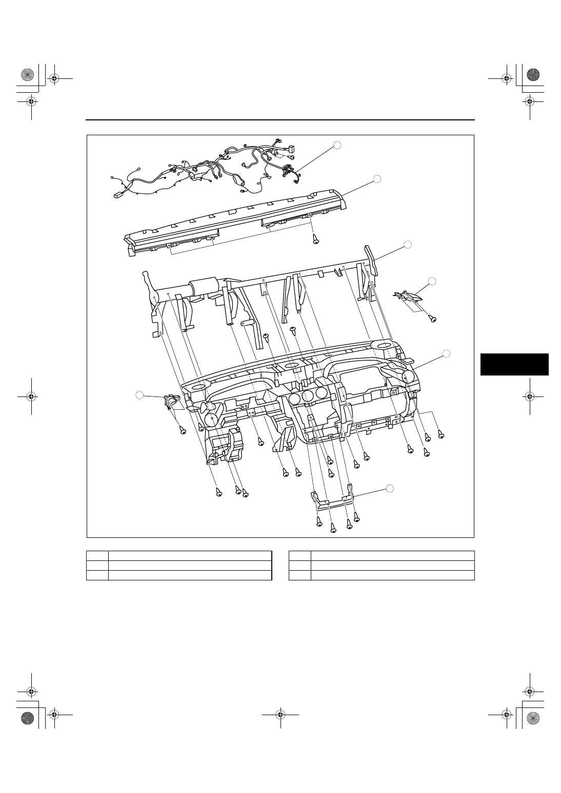
1
Dashboard wiring harness
2
Demister duct
3
Upper garnish
4
Dashboard center panel
5
Dashboard member
6
Dashboard