Mazda CX 7. Manual - part 400


  Index      Mazda     Mazda CX 7 - service repair manual 2007 year


Search            


Content   ..  398  399  400  401   ..


Mazda CX 7. Manual - part 400


SECURITY AND LOCKS 

09-14–35

09-14

STEERING LOCK UNIT ID CODE REGISTRATION[ADVANCED KEYLESS SYSTEM]

id0914008073b1

Caution

• Do not place the following devices in the vehicle while programming, otherwise programming 

cannot be performed.

— M-MDS

— Personal computer

— Device that can send/receive radio waves

Note

• The steering lock unit and steering lock component are a single unit. Therefore, replace the steering lock 

component when replacing steering lock unit. (See 06-14-6 STEERING WHEEL AND COLUMN 
REMOVAL/INSTALLATION.)

• For this procedure, a programmed card key is necessary. If there is no programmed card key, perform the 

steering lock unit programming after the card key programming.

1. Bring the programmed card key into the vehicle.
2. Fully lower the driver-side door glass.
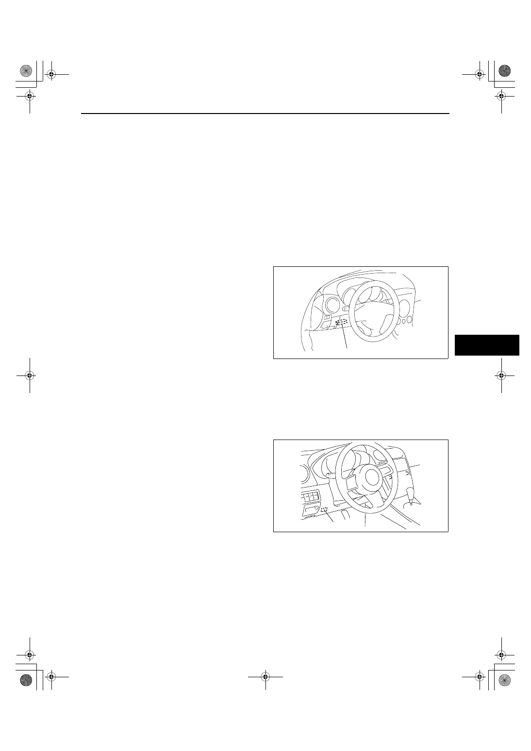
3. Connect the M-MDS to the DLC-2.
4. Pull out the M-MDS cable from the door glass 

opening and set the M-MDS outside the vehicle.

5. Select “BODY/SECURITY/PATS (immobilizer)“ 

from the M-MDS screen menu.

6. Perform the security access according to the 

directions on the M-MDS screen.

7. The security access begins and the M-MDS 

displays “OUT-CODE“.

Note

• When “OUT-CODE” is first displayed, turning 

the ignition switch from the LOCK to the ON 
position 5 times will change the “OUT-
CODE”.

8. Input the “IN-CODE“ that corresponds to the “OUT-CODE“ displayed on the M-MDS screen.
9. Select “STEERING LOCK UNIT PROGRAMMING“ and perform procedures according to the directions on the 

M-MDS screen.

End Of Sie

CUSTOMIZED FUNCTION SETTING PROCEDURE[ADVANCED KEYLESS SYSTEM]

id0914008074b1

1. Connect the M-MDS to the DLC-2.
2. After the vehicle is identified, select the following 

items from the initialization screen of the M-MDS.

• When using the IDS (notebook PC)

1. Select “Module programming”.

• When using the PDS (pocket PC)

1. Select “Programming”.
2. Select “Module programming”.

3. Then, select items from the screen menu in the 

following order.

1. Select “Pragrammable Parameters”.
2. Select “RKE”.

4. Select the item name, and than select either 

“Disable/Enable”.
Items

• Automatic Locks

• Answer Back Buzzer

• Card Key Battery Low Alarm

End Of Sie

DLC-2

acxuuw00002425

DLC-2

acxuuw00002510

SECURITY AND LOCKS 

09-14–36

KEYLESS RECEIVER REMOVAL/INSTALLATION

id091400807500

1. Disconnect the negative battery cable.
2. Remove the glove compartment. (See 09-17-8 GLOVE COMPARTMENT REMOVAL/INSTALLATION.)
3. Disconnect the keyless receiver connector.
4. Remove the bolt, then remove the keyless 

receiver.

5. Install in the reverse order of removal.

End Of Sie

KEYLESS RECEIVER INSPECTION

id091400807600

1. Measure the voltage or inspect for continuity according to the Terminal Voltage Table (Reference).

• If the voltage is not as specified in the Terminal Voltage Table (Reference), inspect the parts under 

“Inspection item(s)” and related wiring harnesses.

2. If the system does not work properly even though the inspection items or related wiring harnesses do not have 

any malfunction, perform symptom troubleshooting [KEYLESS ENTRY SYSTEM].

Terminal Voltage Table (Reference)

End Of Sie

BOLT

CONNECTOR

KEYLESS RECEIVER

acxuuw00002511

Terminal

Signal name

Connected to

Measured condition

Voltage (V)/

Continuity

Inspection item(s)

A

Power supply

ADVANCED 

KEYLESS  
SYSTEM

• Keyless control 

module

KEYLESS ENTRY 

SYSTEM

• BCM

Under any condition

B+

• Keyless control module

• BCM

• Related wiring harnesses

C

Data

ADVANCED 

KEYLESS  
SYSTEM

• Keyless control 

module

KEYLESS ENTRY 

SYSTEM

• BCM

• Under any condition: 

Inspect the wiring 
harness between the 
keyless receiver and 
BCM terminal 7I for 
continuity.

Continuity 

detected

• Keyless control module

• BCM

• Related wiring harnesses

E

GND

Body ground

Under any condition: Inspect 
for continuity to ground.

Continuity 

detected

GND

*

*

*

KEYLESS RECEIVER

WIRING HARNESS-SIDE CONNECTOR

A

C

E

acxuuw00002512

SECURITY AND LOCKS 

09-14–37

09-14

KEYLESS ANTENNA REMOVAL/INSTALLATION[ADVANCED KEYLESS SYSTEM]

id0914008077b1

Exterior, LF/RF

1. Disconnect the negative battery cable.
2. Remove the door trim. (See 09-17-20 FRONT DOOR TRIM REMOVAL/INSTALLATION.)
3. Remove the screws.
4. Disconnect the connector, then remove the 

keyless antenna.

5. Install in the reverse order of removal.

Exterior, Rear

1. Disconnect the negative battery cable.
2. Remove the bolts.
3. Disconnect the connector, then remove the 

keyless antenna.

4. Install in the reverse order of removal.

Interior, Front

1. Disconnect the negative battery cable.
2. Remove the glove compartment. (See 09-17-8 GLOVE COMPARTMENT REMOVAL/INSTALLATION.)
3. Disconnect the connector, then remove the screws.
4. Remove the keyless antenna.
5. Install in the reverse order of removal.

KEYLESS ANTENNA

SCREW

CONNECTOR

acxuuw00002513

KEYLESS 
ANTENNA

CONNECTOR

BOLT

acxuuw00002514

KEYLESS ANTENNA

SCREW

CONNECTOR

acxuuw00002515

SECURITY AND LOCKS 

09-14–38

Interior, Middle

1. Disconnect the negative battery cable.
2. Remove the console. (See 09-17-13 CONSOLE REMOVAL/INSTALLATION.)
3. Remove the clips.
4. Disconnect the connector, then remove the 

keyless antenna.

5. Install in the reverse order of removal.

Interior, Rear

1. Disconnect the negative battery cable.
2. Remove the rear seat. (See 09-13-7 REAR SEAT REMOVAL/INSTALLATION.)
3. Remove the clips.
4. Disconnect the connector, then remove the 

keyless antenna.

5. Install in the reverse order of removal.

End Of Sie

KEYLESS 
ANTENNA

SCREW

CONNECTOR

acxuuw00002516

KEYLESS ANTENNA

CLIP

CONNECTOR

acxuuw00002517


Content   ..  398  399  400  401   ..