Mazda CX 7. Manual - part 393


  Index      Mazda     Mazda CX 7 - service repair manual 2007 year


Search            


Content   ..  391  392  393  394   ..


Mazda CX 7. Manual - part 393


SECURITY AND LOCKS 

09-14–7

09-14

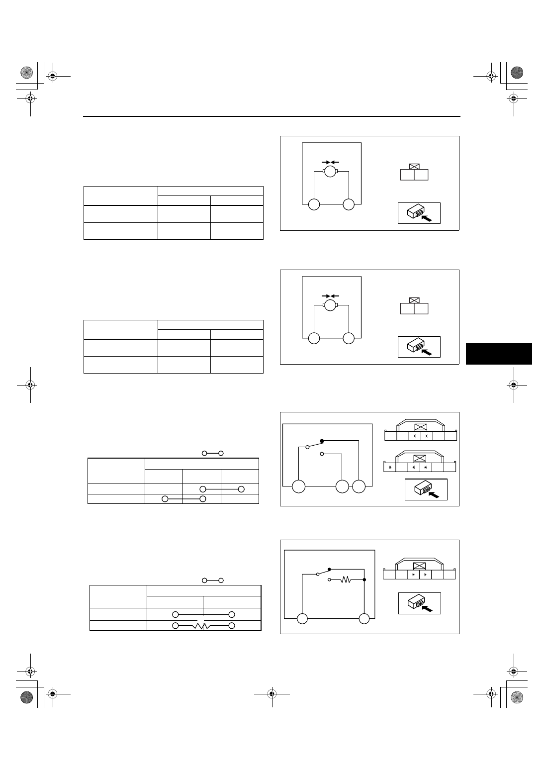
FRONT DOOR LOCK ACTUATOR INSPECTION

id091400800800

1. Apply battery positive voltage and connect ground 

to the corresponding front door lock actuator 
terminals, and inspect the front door lock actuator 
operation.

• If not as specified, replace the front door latch 

and lock actuator.

End Of Sie

REAR DOOR LOCK ACTUATOR INSPECTION

id091400800900

1. Apply battery positive voltage and connect ground 

to the corresponding front door lock actuator 
terminals, and inspect the front door lock actuator 
operation.

• If not as specified, replace the front door latch 

and lock actuator.

End Of Sie

DOOR LOCK-LINK SWITCH INSPECTION

id091400801200

Front/rear

1. Inspect for continuity between the door lock-link 

switch terminals.

• If not as specified, replace the front door latch 

and lock actuator.

End Of Sie

FRONT DOOR KEY CYLINDER SWITCH INSPECTION

id091400801300

1. Inspect for continuity between the front door key 

cylinder switch terminals.

• If not as specified, replace the front door latch 

and lock actuator.

Lock actuator 

operation

Connection

B+

GND

Lock

LH: 1A

RH: 1B

LH: 1B

RH: 1A

Unlock

LH: 1B

RH: 1A

LH: 1A

RH: 1B

1B 

1A 

LOCK UNLOCK

RH: 1B

RH: 1A

1A

1B

acxuuw00002469

Lock actuator 

operation

Connection

B+

GND

Lock

LH: 1A

RH: 1B

LH: 1B

RH: 1A

Unlock

LH: 1B

RH: 1A

LH: 1A

RH: 1B

1B 

1A 

LOCK UNLOCK

RH: 1B

RH: 1A

1A

1B

acxuuw00002470

2E

2B

LOCK

UNLOCK

2F

RH: 2B

RH: 2E

RH: 2A

2E

2F

2A

2B

2E

2B 2A

LH

RH

acxuuw00002471

: Continuity 

Lock knob 

position

Lock

Unlock

Terminal 

LH: 2B
RH: 2E

LH: 2E
RH: 2B

LH: 2F
RH: 2A

acxuuw00002472

2B 

2A

2E

2F

2A

2B

LOCK

UNLOCK

acxuuw00002473

2A

2B

R

R : 1 k ohm

Key cylinder 

position

Lock

Unlock

: Continuity 

Terminal

acxuuw00002474

SECURITY AND LOCKS 

09-14–8

End Of Sie

DOOR LOCK SWITCH REMOVAL/INSTALLATION

id091400801400

1. Disconnect the negative battery cable.
2. Remove the inner handle cover. (See 09-17-20 FRONT DOOR TRIM REMOVAL/INSTALLATION.)
3. Remove the screws, then remove the door lock 

switch.

4. Install in the reverse order of removal.

End Of Sie

DOOR LOCK SWITCH INSPECTION

id091400801500

1. Inspect for continuity between the door lock 

switch terminals using an ohmmeter.

• If not as specified, replace the door lock 

switch.

End Of Sie

DOOR LOCK STRIKER REMOVAL/INSTALLATION

id091400801600

1. Remove the screws, then remove the door lock 

striker.

2. Install in the reverse order of removal.
3. Adjust the door. (See 09-11-3 DOOR 

ADJUSTMENT.)

End Of Sie

WM: OPEN HANDLE

FRONT OUTER HANDLE REMOVAL/INSTALLATION

id091400803100

1. Disconnect the negative battery cable.
2. Fully roll up the front door glass.
3. Remove the inner garnish. (See 09-17-20 INNER GARNISH REMOVAL/INSTALLATION.)
4. Remove the front door trim. (See 09-17-20 FRONT DOOR TRIM REMOVAL/INSTALLATION.)
5. Remove the hole cover.
6. Detach the rod from the outer handle.

DOOR LOCK
SWITCH

SCREW

acxuuw00002475

UNLOCK

LOCK

C

D

B

A

A

B

C

D

acxuuw00002476

R: 940—1,060 ohms

D

C

: Continuity

Lock

Unlock

Position

Terminal

: Resistance

R

acxuuw00002477

SCREW

17.6—26.5 N·m

{1.80—2.70 kgf·m,
13.0—19.5 ft·lbf}

DOOR LOCK STRIKER

acxuuw00002478

SECURITY AND LOCKS 

09-14–9

09-14

7. Secure the rear part of the front outer handle and, 

with the front outer handle lever pulled outward 
(1), remove the rear part of the front outer handle 
from the front door.

8. Pull out the front side of the front outer handle 

from the front door.

9. Install in the reverse order of removal.

End Of Sie

REAR OUTER HANDLE REMOVAL/INSTALLATION

id091400803200

1. Disconnect the negative battery cable.
2. Fully roll up the rear door glass.
3. Remove the rear door trim. (See 09-17-23 REAR DOOR TRIM REMOVAL/INSTALLATION.)
4. Secure the rear part of the rear outer handle and, 

with the rear outer handle lever pulled outward 
(1), remove the rear part of the rear outer handle 
from the rear door.

5. Install in the reverse order of removal.

End Of Sie

INNER HANDLE REMOVAL/INSTALLATION

id091400803300

1. Disconnect the negative battery cable.
2. Remove the front door trim or rear door trim. (See 09-17-20 FRONT DOOR TRIM REMOVAL/INSTALLATION.) 

(See 09-17-23 REAR DOOR TRIM REMOVAL/INSTALLATION.) 

3. Detach the cables from the inner handle and door 

lock knob.

4. Install in the reverse order of removal.

End Of Sie

WM: LIFTGATE LOCK

LIFTGATE OUTER HANDLE REMOVAL/INSTALLATION

id091400803700

1. Remove the rear finisher. (See 09-16-3 REAR FINISHER REMOVAL/INSTALLATION.)
2. Remove in the order indicated in the table.

3. Install in the reverse order of removal.

End Of Sie

OUTER HANDLE

FRONT

(1)

acxuuw00002479

OUTER HANDLE

FRONT

(1)

acxuuw00002480

INNER 
HANDLE

CABLE

acxuuw00002481

1

Nut

2

Liftgate outer handle

3.9—5.9 N·m 
{39.8—60.1 kgf·cm, 
34.6—52.2 in·lbf}

1

2

acxuuw00002482

SECURITY AND LOCKS 

09-14–10

LIFTGATE LATCH AND LOCK ACTUATOR REMOVAL/INSTALLATION

id091400803800

1. Disconnect the negative battery cable.
2. Remove in the order indicated in the table.

3. Install in the reverse order of removal.

End Of Sie

LIFTGATE LOCK ACTUATOR INSPECTION

id091400803900

1. Apply battery positive voltage and connect ground 

to the corresponding liftgate lock actuator 
terminals, and inspect the liftgate lock actuator 
operation.

• If not as specified, replace the liftgate latch 

and lock actuator.

End Of Sie

LIFTGATE LATCH SWITCH INSPECTION

id091400804000

1. When inspecting the latch, press the latch lever 

using a flathead screwdriver or a similar tool.

2. Inspect for continuity between the liftgate latch 

switch terminals.

• If not as specified, replace the liftgate latch 

and lock actuator.

End Of Sie

1

Bolt

2

Connector

3

Liftgate latch and lock actuator

A

A

B

B

C

C

6.90—9.80 N·m {70—100 kgf·cm, 60.8—86.7 in·lbf}

3

1

2

acxuuw00002483

Lock actuator 

operation

Connection

B+

GND

Lock

A

B

Unlock

B

A

A

B

A

LOCK UNLOCK

acxuuw00002484

LEVER

acxuuw00002485

A

B

B

A

acxuuw00002486

: Continuity 

Latch condition

Terminal 

B

A

Latch (liftgate is closed)

Unlatch (liftgate is open)

acxuuw00002487


Content   ..  391  392  393  394   ..