Mazda CX 7. Manual - part 299


  Index      Mazda     Mazda CX 7 - service repair manual 2007 year


Search            


Content   ..  297  298  299  300   ..


Mazda CX 7. Manual - part 299


CONTROL SYSTEM 

07-40–21

07-40

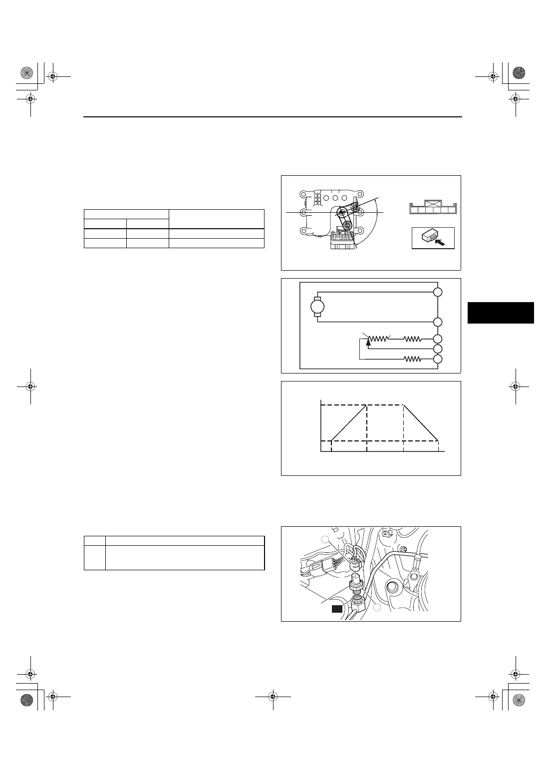
AIR MIX ACTUATOR INSPECTION

id074000802500

Caution

• If the lever position exceeds the operation range shown in the figure, the circuit in the actuator 

could be damaged. Always perform an actuator operation with the lever movement within the 
range shown in the figure.

1. Connect battery positive voltage to terminal D or F and ground to terminal F or D of the air mix actuator.
2. Verify that the air mix actuator operates as shown 

below.

• If there is any malfunction, replace the air mix 

actuator.

3. Verify that the resistance between the terminals of 

the air mix actuator are as shown in the graph.

• If there is any malfunction, replace the air mix 

actuator.

End Of Sie

WM: REFRIGERANT PRESSURE SWITCH

REFRIGERANT PRESSURE SWITCH REMOVAL/INSTALLATION

id074000802600

1. Disconnect the negative battery cable.
2. Discharge the refrigerant from the system. (See 07-10-6 REFRIGERANT RECOVERY.) (See 07-10-2 

REFRIGERANT CHARGING.)

3. Loosen the refrigerant pressure switch using two spanners.
4. Remove in the order indicated in the table.

5. Install in the reverse order of removal.
6. Perform the refrigerant system performance test. 

(See 07-10-6 REFRIGERANT SYSTEM 
PERFORMANCE TEST.)

Refrigerant Pressure Switch Installation Note

1. Apply compressor oil to O-ring and connect the joint.

End Of Sie

Connection

Movement

B+

GND

D

F

HOT 

→ COLD

F

D

COLD 

→ HOT

67.5

°

22.5

°

F

D

A

B

*

C

MAX COLD

MAX HOT

acxuuw00001567

M

F

D

B

C

A

MAX HOT

MAX COLD

acxuuw00000736

MAX
HOT

MAX
COLD

MAX
COLD

MAX
HOT

0.5

3.5

RESIST

ANCE

KILOHM

BETWEEN A
AND C
TERMINALS WIRE

BETWEEN C
AND B
TERMINALS WIRE

AIR MIX ACTUATOR POSITION

acxuuw00000737

1

Refrigerant pressure switch connector

2

Refrigerant pressure switch
(See 07-40-21 Refrigerant Pressure Switch 
Installation Note.)

N·m {kgf·cm, in·lbf}

8.82—10.78
{90.0—109.9,
78.1—95.3}

1

2

R

acxuuw00001571

1871-1U-06B(07-40).fm  21 ページ  2006年3月16日 木曜日 午後4時1分

CONTROL SYSTEM 

07-40–22

REFRIGERANT PRESSURE SWITCH INSPECTION

id074000802700

1. Install the manifold gauge.
2. Disconnect the refrigerant pressure switch connector.
3. Verify the high-pressure side reading of the 

manifold gauge and continuity between the 
terminals of the refrigerant pressure switch.

• If the continuity is not normal, replace the 

refrigerant pressure switch.

End Of Sie

WM: SOLAR RADIATION SENSOR

SOLAR RADIATION SENSOR REMOVAL/INSTALLATION

id074000802800

1. Disconnect the negative battery cable.

2. Remove the dashboard under cover (driver’s side).

3. Press out the solar radiation sensor with its connector from under the instrument panel.

4. Remove in the order indicated in the table.

5. Install in the reverse order of removal.

HIGH AND LOW PRESSURE SWITCH

BETWEEN B AND C TERMINALS

CONTINUITY

NO CONTINUITY

0.176—0.216
{1.795—2.202, 25.53—31.31}

2.94—3.34
{30.0—34.0, 427—483}

0.02 {0.20, 2.84}
or less

0.39—0.79
{3.98—8.05, 56.6—114}

0.195—0.250
{1.989—2.549,
28.30—36.24}

MPa {kgf/cm

2

, psi}

A6E8540W053

MPa {kgf/cm

2

, psi}

1.08—1.38
{11.1—14.0, 158—199}

1.39—1.65
{14.2—16.8, 202—238}

MEDIUM-PRESSURE SWITCH

BETWEEN A AND D TERMINALS

CONTINUITY

NO CONTINUITY

E6U740ZWB105

A

B

C

D

B

A

C

D

HIGH AND LOW
PRESSURE

MEDIUM PRESSURE

CHU0740W024

1

2

acxuuw00000982

1

Solar radiation sensor connector

2

Solar radiation sensor

1871-1U-06B(07-40).fm  22 ページ  2006年3月16日 木曜日 午後4時1分

CONTROL SYSTEM 

07-40–23

07-40

End Of Sie

SOLAR RADIATION SENSOR INSPECTION

id074000802900

1. Shine a fluorescent light or expose the solar radiation sensor to natural sunlight.
2. Connect the positive (+) lead to terminal A and 

the negative (

−) lead to terminal B of the solar 

radiation sensor, and verify that the voltages are 
as shown in the table.

• If the voltage is not as specified, replace the 

solar radiation sensor.

End Of Sie

WM: CABIN TEMPERATURE SENSOR

PASSENGER COMPARTMENT TEMPERATURE SENSOR REMOVAL/INSTALLATION

id074000803000

1. Disconnect the negative battery cable.
2. Remove the following parts:

(1) Front scuff plate inner (driver's side). (See 09-17-19 FRONT SCUFF PLATE REMOVAL/INSTALLATION.)
(2) Front side trim (driver's side). (See 09-17-18 FRONT SIDE TRIM REMOVAL/INSTALLATION.)
(3) Console panel. (See 09-17-15 CONSOLE PANEL REMOVAL/INSTALLATION.)
(4) Console. (See 09-17-13 CONSOLE REMOVAL/INSTALLATION.)
(5) Hood release lever. (See 09-14-25 HOOD LATCH AND RELEASE LEVER REMOVAL/INSTALLATION.)
(6) Lower panel (See 09-17-9 LOWER PANEL REMOVAL/INSTALLATION.)

3. Remove in the order indicated in the table.

4. Install in the reverse order of removal.

End Of Sie

PASSENGER COMPARTMENT TEMPERATURE SENSOR INSPECTION

id074000803100

1. Measure the temperature around the passenger compartment temperature sensor.
2. Measure the resistance between terminals of the 

passenger compartment temperature sensor.

• If the resistance is not as shown in the graph, 

replace the passenger compartment 
temperature sensor.

End Of Sie

WM: AMBIENT TEMPERATURE SENSOR

V

A

B

A

B

acxuuw00002540

Voltage (V)

Test condition

: Continuity 

Sensor subject to fluorescent 
light or natural sunlight

Sensor covered by a cloth

0.1

0.45

0.1 or less

acxuuw00002541

1

Air  hose

2

Passenger compartment temperature sensor 
connector

3

Passenger compartment temperature sensor

3

1

2

acxuuw00000745

°C {°F}

RESIST

ANCE

KILOHM

0

2

4

6

8

10

12

14

16

18

20

-10
{14}

0
{32}

10
{50}

20
{68}

30
{86}

40
{104}

50
{122}

TEMPERATURE

A6E8540W021

1871-1U-06B(07-40).fm  23 ページ  2006年3月16日 木曜日 午後4時1分

CONTROL SYSTEM 

07-40–24

AMBIENT TEMPERATURE SENSOR REMOVAL/INSTALLATION

id074000803200

1. Disconnect the negative battery cable.
2. Remove the under cover.
3. Remove in the order indicated in the table.

4. Install in the reverse order of removal.

End Of Sie

AMBIENT TEMPERATURE SENSOR INSPECTION

id074000803300

Note

• Ambient temperature sensor does not detect a sudden change in temperature sensitively caused by 

driving or stopping the vehicle to stabilize the control of the full-auto air conditioner. Therefore, the 
measured value may differ from the original value when the resistance of the ambient temperature sensor 
is measured immediately after the removal.

1. After removing the ambient temperature sensor, leave it to the inspection place for 30 min or more.
2. Measure the temperature around the ambient temperature sensor.
3. Measure the resistance between terminals of the 

ambient temperature sensor.

• If the resistance is not as shown in the graph, 

replace the ambient temperature sensor.

End Of Sie

SOKYU_WM: CLIMATE CONTROL UNIT

1

Ambient temperature sensor connector

2

Ambient temperature sensor

1

2

acxuuw00000746

16

14

12

10

8

6

4

2

0

-10
{14}

{32}

{50}

{68}

{86}

{104}

{122}

0

TEMPERATURE

KILOHM

RESIST

ANCE

10

20

30

40

50

{  F}

C

acxuuw00000984

1871-1U-06B(07-40).fm  24 ページ  2006年3月16日 木曜日 午後4時1分


Content   ..  297  298  299  300   ..