Mazda CX 7. Manual - part 298
CONTROL SYSTEM
07-40–17
07-40
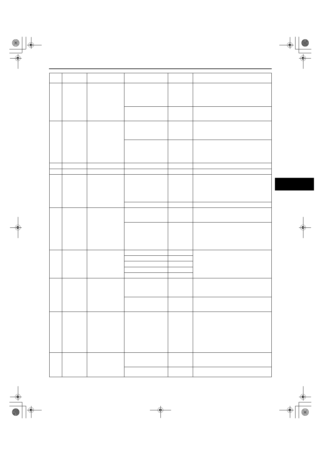
Term
inal
Signal
name
Connected to
Measurement
condition
Voltage (V)
Inspection item (s)
A
Illumination
control
Instrument cluster
Headlight switch ON
and panel light control
switch at max
0.45
• Wiring harness: continuity (Climate
control unit— instrument cluster: A—
2H) (Instrument cluster— body ground:
2A— GND)
• Instrument cluster
Headlight switch ON
and panel light control
switch at min
9.96
• Wiring harness: short circuit (Climate
control unit— instrument cluster: A—
2H)
B
TNS signal
TNS relay
Headlight switch OFF
1.0 or less
• Wiring harness: short circuit (Climate
control unit— TNS relay: B— C)
• TNS relay
• Headlight switch
Headlight switch ON
B+
• Wiring harness: continuity, short circuit
(Climate control unit— TNS relay: B—
C)
• TNS relay
• Headlight switch
C
— —
— —
—
D
— —
— —
—
E
+5V
Airflow mode
actuator
IG SW ON
4.91
• Wiring harness: short circuit (Climate
control unit—airflow mode actuator: E—
B)
• Airflow mode actuator
• Climate control unit: terminal voltage (R,
L)
IG SW OFF
1.0 or less
• Climate control unit replacement
F
FAN ON/
OFF
Airflow volume
control dial
Airflow volume control
dial ON
0.06
• Wiring harness: (Climate control unit—
airflow volume control dial: F— C)
• Airflow volume control dial
Airflow volume control
dial OFF
12.18
• Wiring harness: continuity (Climate
control unit— airflow volume control
dial: F— C)
• Climate control unit: terminal voltage
(R)
• Airflow volume control dial
G
Potentiomet
er input
Airflow mode
actuator
VENT
4.20
• Wiring harness: continuity, short circuit
(Climate control unit— airflow mode
actuator: G— C)
• Airflow mode actuator
• Climate control unit: terminal voltage (E)
BILEVEL
3.34
HEAT
2.44
HEAT/DEF
1.56
DEFROSTER
0.68
H
Rear
window
defroster
switch
Rear window
defroster relay
Rear window defroster
switch OFF
B+
• Wiring harness: continuity, short circuit
(Climate control unit— rear window
defroster relay: H— E)
• Rear window defroster relay
Rear window defroster
switch ON
0.06
• Climate control unit: terminal voltage (L,
R)
• Climate control unit:
I
Evaporator
temperature
sensor input
Evaporator
temperature sensor
Compared with
temperature detected
by evaporator
temperature sensor
Refer to
graph 2
• Wiring harness: continuity (Climate
control unit—evaporator temperature
sensor: I—B, K—A)
• Wiring harness: short circuit (Climate
control unit—evaporator temperature
sensor: I—B)
• Evaporator temperature sensor
• Climate control unit: terminal voltage (L,
R)
J
A/C
BCM
A/C switch ON, airflow
volume control dial at
1st
0.03
• Wiring harness: continuity (Climate
control unit— BCM: J— 3V)
• BCM
A/C switch OFF
5.02
• Wiring harness: continuity, short circuit
(Climate control unit— BCM: J— 3V)
1871-1U-06B(07-40).fm 17 ページ 2006年3月16日 木曜日 午後4時1分