Mazda CX 7. Manual - part 275


  Index      Mazda     Mazda CX 7 - service repair manual 2007 year


Search            


Content   ..  273  274  275  276   ..


Mazda CX 7. Manual - part 275


POWER STEERING 

06-14–17

06-14

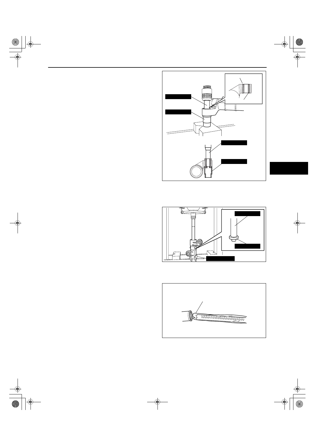
4. Reverse the gear housing, then press the 

mounting rubber until the mounting rubber end 
comes out completely from the other side. At this 
time, make sure that the mounting rubber and 
steel pipe are aligned.

Oil Seal Assembly Note

1. Apply ATF to the lip of a new oil seal.
2. Install the SST (49 N032 319A) to the gear housing with the raised part facing up as shown in the figure.
3. Set the stopper into the gear housing to hold the 

SSTs as shown in the figure.

4. Install the oil seal using the SSTs (49 F032 303, 

49 H032 326) and a press.

Steering Rack Assembly Note

1. Apply multipurpose grease to the rack teeth.
2. Install a plastic bag to the rack teeth and insert 

the steering rack in the gear housing.

STEEL PIPE

MOUNTING RUBBER

49 B018 003

49 B018 003

49 B032 317

49 B032 317

acxuuw00000997

49 F032 303

49 H032 326

49 N032 319A

acxuuw00000998

PLASTIC BAG

acxuuw00000999

1871-1U-06B(06-14).fm  17 ページ  2006年3月15日 水曜日 午前11時25分

POWER STEERING 

06-14–18

Stopper Assembly Note

1. Using an appropriate pipe and a hammer, insert 

the rack stopper into the gear housing until the 
clip installation groove of the gear housing comes 
out.

2. Apply 53.3 kPa {400 mmHg, 15.8 inHg} vacuum 

with a vacuum pump and verify that it is held for 
30 s.

• If the vacuum is not held, replace the oil seal.

Oil seal (Upper side) Assembly Note 

1. Assemble the oil seal (upper side) using the SST.

Substitution SST

• 49 H032 327

Outer diameter: 30— 34 mm {1.2— 1.3 in}

• 49 H032 334

Outer diameter: 30— 32 mm {1.19— 1.25 in}

Bearing (upper side) Assembly Note 

1. Assemble the bearing (upper side) using the SST.

Substitution SST

• 49 H032 327

Outer diameter: 30— 34 mm {1.2— 1.3 in}

acxuuw00001000

49 G032 3A1

acxuuw00001001

49 H032 327

49 H032 334

acxuuw00001002

49 H032 327

acxuuw00001003

1871-1U-06B(06-14).fm  18 ページ  2006年3月15日 水曜日 午前11時25分

POWER STEERING 

06-14–19

06-14

2007 Mazda CX-7 Workshop Manual (1871–1U–06B)

Revised 7/2006 (Ref. No. R065/06) 

Oil Seal (lower side) Assembly Note

1. Assemble the oil seal (lower side) using the SST.

Substitution SST

• 49 L032 312A

Outer diameter: 35— 36 mm {1.2— 1.3 in}
Cylindrical shape outer diameter of 40 mm 
{1.6 in} or more.

Pinion Shaft Assembly Note

1. Assemble the pinion shaft using a press.

Housing Cover Assembly Note

1. Apply silicone sealant to the threads of the housing cover.
2. Assemble the housing cover.

Dust cover Assembly Note 

1. Apply grease to the oil dust cover shown in the 

figure.

Specified grease

• Rubber grease (Mazda genuine parts) or 

equivalent.

Adjusting Cover, Locknut (Adjusting Cover) Assembly Note

1. Install two nuts to the bolt across a flat 24 mm 

{0.94 in} and tighten them using a wrench.

2. Using the bolt/nut produced in Step 1, install the 

adjusting cover.
(1) Tighten the adjusting cover with a tightening 

torque of 20.0 N·m {2.0 kgf·m, 14.8 ft·lbf}.

49 L032 312A

acxuuw00001007

acxuuw00001006

GREASE

acxuuw00002261

ACROSS FLAT 24 mm {0.94 in}

NUT

BOLT

acxuuw00002544

POWER STEERING 

06-14–20

2007 Mazda CX-7 Workshop Manual (1871–1U–06B)

Revised 7/2006 (Ref. No. R065/06)

(2) Using the SST, loosen the adjusting cover to 

25—30

°.

3. Apply sealant to the locknut.

4. Secure the adjusting cover with the bolt and nuts 

created in Step 1, and tighten the locknut using 
the SST.

Caution

• If a tool such as a torque wrench is 

installed to the SST (49 E032 308), install 
the tool so that it is perpendicular to the 
SST as shown in the figure. If the tool is 
not installed as instructed, the SST can 
separate from the locknut easily which 
could cause damage to the locknut while 
doing the work.

Note

• Be sure that the adjusting cover will not turn 

together with the locknut.

5. Measure the pinion torque using the SST and pull 

scale.

• If not as specified, remove the locknut and 

adjust the adjusting cover.

Pinion shaft rotation torque

Center of rack 

±90°:0.88—1.48 N·m {8.98—

15.0 kgf·cm, 7.79—13.0 in·lbf}

Tie-rod Assembly Note

1. Lock the steering rack end against rotation with a 

suitable wrench and install the tie rod using the 
SST.
Substitution SST

• 49 H032 351

Width across flats 34mm {1.3 in} (Torque 
control enabled wrench)

49 D032 316

acxuuw00001008

49 E032 308

49 E032 308

ACROSS FLAT 24 mm {0.94 in}

NUT

BOLT

acxuuw00002548

acxuuw00002345

49 H032 351

acxuuw00001725


Content   ..  273  274  275  276   ..