Mazda CX 7. Manual - part 263


  Index      Mazda     Mazda CX 7 - service repair manual 2007 year


Search            


Content   ..  261  262  263  264   ..


Mazda CX 7. Manual - part 263


AUTOMATIC TRANSAXLE [AW6A-EL, AW6AX-EL]

05-17–41

05-17

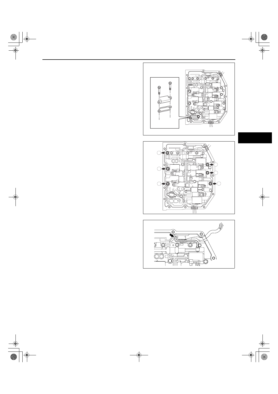
16. Remove the suction cover and the gasket.

Caution

• Evenly loosen the bolts a little at a time in 

the order shown in the figure.

17. Remove the control valve body installation bolts.

Caution

• Do not drop the control valve body 

component.

18. Disconnect the manual valve link and remove the 

control valve body component.

acxuuw00000594

5

4

3

6

1

2

acxuuw00000595

acxuuw00000596

1871-1U-06B(05-17).fm  41 ページ  2006年3月15日 水曜日 午前11時20分

AUTOMATIC TRANSAXLE [AW6A-EL, AW6AX-EL]

05-17–42

On-Vehicle Installation

Caution

• When installing the control valve body component, do not put the coupler component in the open 

space of the separate plate in the control valve body component.

• Do not pinch the coupler component between the separate plate and the control valve body 

component.

1. Connect the manual valve link and install the 

control valve body component.

2. Temporarily install the control valve body 

component with the bolts.

Bolt length (measured from below the head)

A: 31 mm {1.220 in}
B: 17 mm {0.669 in}
C: 21 mm {0.827 in}

Note

• Aligning the bolt holes, temporarily tighten 

the bolt by hand.

3. Temporarily install the suction cover and a new 

gasket with the bolts.

SEPARATE PLATE

acxuuw00000597

A

B

B

B

C

C

acxuuw00000598

acxuuw00000594

1871-1U-06B(05-17).fm  42 ページ  2006年3月15日 水曜日 午前11時20分

AUTOMATIC TRANSAXLE [AW6A-EL, AW6AX-EL]

05-17–43

05-17

4. Tighten the bolts in the order shown in the figure.

Tightening torque

8— 12 N·m {82— 122 kgf·cm, 72— 105 in·lbf}

5. Install the connector of the VSS and input/turbine 

speed sensor to the solenoid clamp.

Caution

• If the control valve body cover is installed with the wiring harnesses overlapped, the wiring 

harnesses may be pinched between the cover and valve body causing the wiring harnesses to be 
damaged. Therefore, verify that the wiring harnesses are not overlapped when installing the 
control valve body cover.

6. Apply ATF to a new O-ring and install it on the TFT sensor.

2

3

4

1

6

5

7

8

acxuuw00000599

VSS CONNECTOR

INPUT/TURBINE SPEED SENSOR 
CONNECTOR

acxuuw00000592

NO GOOD

GOOD

acxuuw00000600

1871-1U-06B(05-17).fm  43 ページ  2006年3月15日 水曜日 午前11時20分

AUTOMATIC TRANSAXLE [AW6A-EL, AW6AX-EL]

05-17–44

7. Install the TFT sensor with the lock plate and a 

bolt to the control valve body component as 
shown in the figure.

Tightening torque

8— 12 N·m {82— 122 kgf·cm, 72— 105 in·lbf}

8. Connect the solenoid connectors, VSS connector 

and the input/turbine speed sensor connector.

9. Connect the coupler component to the clamps.

Note

• Completely remove sealant and oil with 

white gasoline or similar.

10. Clean sealant and oil off the contact surface of 

the transaxle case with the control valve body 
cover and the bolt holes.

Note

• Completely remove oil with white gasoline or 

similar.

11. Clean oil off the contact surface of the new control 

valve body cover with the transaxle case.

acxuuw00000601

CLAMP

CLAMP

acxuuw00000589

acxuuw00000602

1871-1U-06B(05-17).fm  44 ページ  2006年3月15日 水曜日 午前11時20分


Content   ..  261  262  263  264   ..