Mazda CX 7. Manual - part 218


  Index      Mazda     Mazda CX 7 - service repair manual 2007 year


Search            


Content   ..  216  217  218  219   ..


Mazda CX 7. Manual - part 218


DYNAMIC STABILITY CONTROL 

04-15–3

04-15

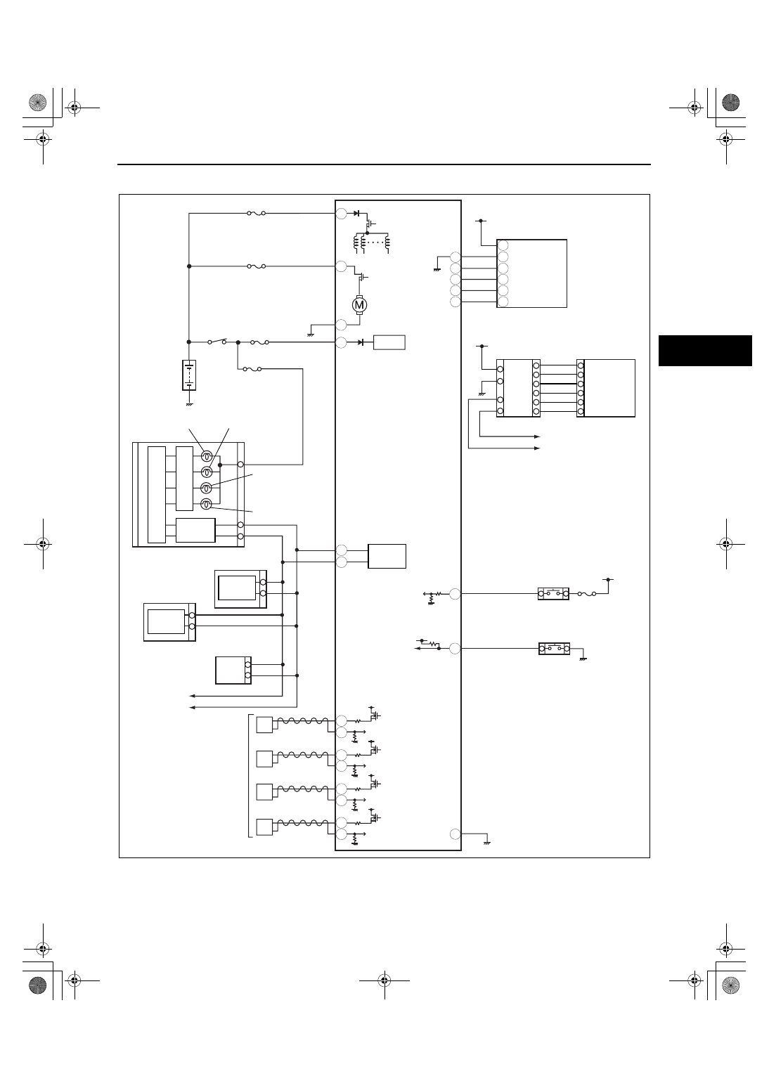
DSC SYSTEM WIRING DIAGRAM

id041500800600

End Of Sie

AE

AA

Y

AB

D

AI

B

I

O

N

P

M

F
E

L

G
H

A

X

W

J

C

E

C

F

A
B
D

BRAKE SWITCH

TSC OFF SWITCH

COMBINED 
SENSOR

STEERING 
ANGLE 
SENSOR

ABS 1 40A

ABS 2 20A

IG 1

CAN_H

CAN_L

BCM

ABS WHEEL-
SPEED SENSOR

RF

LF

RR

LR

CAN 
DRIVER

CAN 
DRIVER

PCM

TCM

CAN 
DRIVER

CAN_H

CAN_L

CAN_H

CAN_L

DLC-2

CAN 
DRIVER

BRAKE SYSTEM 
WARNING LIGHT

ABS WARNING 
LIGHT

TSC OFF LIGHT

DSC INDICATOR 
LIGHT

DSC HU/CM

INSTRUMENT CLUSTER

IG SW

BATTERY

DSC 7.5A

acxuuw00002206

1871-1U-06B(04-15).fm  3 ページ  2006年3月15日 水曜日 午前11時16分

DYNAMIC STABILITY CONTROL 

04-15–4

DSC SYSTEM INSPECTION

id041500800700

Preparation

1. Verify that battery is fully charged.
2. Turn the ignition switch to the ON position, and verify that the ABS warning light goes out after approx. 3 s.
3. Turn the ignition switch off.
4. Jack up the vehicle and support it evenly on safety stands.
5. Shift to the N position.
6. Verify that all four wheels rotate.
7. Rotate the inspected wheels by hand, and verify there is no brake drag.

• If there is any brake drag, perform regular brake inspection.

• If there is no brake drag, perform DSC HU/CM operation inspection.

ABS Control Inspection

1. Perform “Preparation”.
2. Connect the M-MDS to the DLC-2.
3. Set up an active command mode inspection 

according to the combination of commands 
below.

DLC-2

acxuuw00001209

1871-1U-06B(04-15).fm  4 ページ  2006年3月15日 水曜日 午前11時16分

DYNAMIC STABILITY CONTROL 

04-15–5

04-15

Brake pressure retention

Brake pressure reduction

Caution

• To protect the DSC HU/CM, the solenoid valve and the pump motor used during active command 

mode stay on for only 10 s or less each time they are switched on.

Note

• When working with two people, one should press on the brake pedal, and the other should attempt to 

rotate the wheel being inspected.

4. Send the command while depressing on the brake pedal and attempting to rotate the wheel being inspected.
5. While brake pressure is maintained and a DSC HU/CM operation click sound is heard, confirm that the wheel 

does not rotate. While brake pressure is being reduced and an DSC HU/CM operation click sound is heard, 
confirm that the wheel rotates.

• Performing the inspection above determines the following:

— The DSC HU/CM brake lines are normal.

— The DSC HU/CM hydraulic system is not significantly abnormal (including DSC HU/CM).

— The DSC HU/CM internal electrical parts (solenoid, motor and other parts) are normal.

— The DSC unit and DSC HU/CM output system wiring harnesses (solenoid valve, relay system) are 

normal.

• However, the following items cannot be verified.

— Malfunction with intermittent occurrence of the above items

— Malfunction of DSC HU/CM input system wiring harnesses and parts

— Extremely small leaks in the DSC HU/CM internal hydraulic system

Command name

Inspected wheels

LF

RF

LR

RR

V_TRC_L

OFF

V_TRC_R

V_STB_L

V_STB_R

LF_INLET

ON

OFF

OFF

OFF

LF_OUTLET

OFF

LR_INLET

ON

LR_OUTLET

OFF

RF_INLET

ON

RF_OUTLET

OFF

RR_INLET

ON

RR_OUTLET

OFF

PMP_MOTOR

Command name

Inspected wheels

LF

RF

LR

RR

V_TRC_L

OFF

V_TRC_R

V_STB_L

V_STB_R

LF_INLET

ON

OFF

OFF

OFF

LF_OUTLET

LR_INLET

OFF

ON

LR_OUTLET

RF_INLET

ON

OFF

RF_OUTLET

RR_INLET

OFF

ON

RR_OUTLET

PMP_MOTOR

ON

1871-1U-06B(04-15).fm  5 ページ  2006年3月15日 水曜日 午前11時16分

DYNAMIC STABILITY CONTROL 

04-15–6

DSC Control Inspection

1. Perform “Preparation”.
2. Connect the M-MDS to the DLC-2.
3. Set up an active command mode inspection 

according to the combination of commands 
below.

Caution

• To protect the DSC HU/CM, the solenoid 

valve and the pump motor used during 
active command mode stay on for only 10 
s or less each time they are switched on.

4. Send the command while rotating the wheel being inspected by hand in a forward direction.
5. Confirm that the wheel does not rotate easily while a DSC HU/CM operation click sound is heard.

• Performing the inspection above determines the following:

— The DSC HU/CM brake lines are normal.

— The DSC HU/CM hydraulic system is not significantly abnormal (including DSC HU/CM).

— The DSC HU/CM internal electrical parts (solenoid, motor and other parts) are normal.

— The DSC unit and DSC HU/CM output system wiring harnesses (solenoid valve, relay system) are 

normal.

• However, the following items cannot be verified.

— Malfunction with intermittent occurrence of the above items

— Malfunction of DSC HU/CM input system wiring harnesses and parts

— Extremely small leaks in the DSC HU/CM internal hydraulic system

End Of Sie

DSC HU/CM REMOVAL/INSTALLATION

id041500801000

Caution

• The DSC may not function normally when the DSC HU/CM is replaced. After installation, always 

perform the initialization procedures for the DSC HU/CM, combined sensor and the steering angle 
sensor. (See 04-15-17 COMBINED SENSOR INITIALIZATION PROCEDURE.) (See 09-40-8 
STEERING ANGLE SENSOR INITIALIZATION PROCEDURE.)

• The internal parts of the DSC HU/CM could be damaged if dropped. Be careful not to drop the DSC 

HU/CM. Replace the DSC HU/CM if it is subjected to an impact.

1. Remove the battery and battery tray. (See 01-17-2 BATTERY REMOVAL/INSTALLATION[L3 WITH TC].)

DLC-2

acxuuw00001209

Command name

Inspected wheels

Understeer control inhibited

Oversteer control inhibited

LF

RF

LR

RR

V_TRC_L

ON

OFF

ON

V_TRC_R

OFF

ON

OFF

V_STB_L

OFF

V_STB_R

LF_INLET

OFF

OFF

OFF

ON

LF_OUTLET

OFF

LR_INLET

ON

LR_OUTLET

OFF

RF_INLET

ON

RF_OUTLET

OFF

RR_INLET

ON

RR_OUTLET

OFF

PMP_MOTOR

ON

1871-1U-06B(04-15).fm  6 ページ  2006年3月15日 水曜日 午前11時16分


Content   ..  216  217  218  219   ..