Mazda CX 7. Manual - part 214
PARKING BRAKE SYSTEM
04-12–1
04-12
04-12
PARKING BRAKE SYSTEM
PARKING BRAKE SYSTEM
LOCATION INDEX . . . . . . . . . . . . . . . . 04-12–1
PARKING BRAKE INSPECTION . . . . . . 04-12–2
PARKING BRAKE ADJUSTMENT . . . . . 04-12–2
PARKING BRAKE
REMOVAL/INSTALLATION[2WD] . . . . 04-12–3
End Cable Removal Note. . . . . . . . . . . 04-12–5
Brake Caliper Component
Removal Note . . . . . . . . . . . . . . . . . . 04-12–5
Disc Plate Removal Note . . . . . . . . . . . 04-12–5
Parking Brake Shoe Removal Note . . . 04-12–6
Operation lever, Pin, Adjuster
Bolt and Nut, Tappet
Installation Note . . . . . . . . . . . . . . . . 04-12–6
Parking Brake Shoe
Installation Note . . . . . . . . . . . . . . . . 04-12–6
Disc Plate, Screw Installation Note . . . 04-12–7
End Cable Installation Note. . . . . . . . . . 04-12–7
PARKING BRAKE
REMOVAL/INSTALLATION[AWD] . . . . 04-12–8
End Cable Removal Note . . . . . . . . . . . 04-12–10
Brake Caliper Component
Removal Note . . . . . . . . . . . . . . . . . . . 04-12–10
Disc Plate Removal Note . . . . . . . . . . . 04-12–10
Parking Brake Shoe Removal Note. . . . 04-12–11
Operation lever, Pin, Adjuster Bolt
and Nut, Tappet Installation Note . . . . 04-12–11
Parking Brake Shoe
Installation Note . . . . . . . . . . . . . . . . . 04-12–11
Disc Plate, Screw Installation Note . . . . 04-12–12
End Cable Installation Note. . . . . . . . . . 04-12–13
PARKING BRAKE SWITCH
INSPECTION . . . . . . . . . . . . . . . . . . . . . 04-12–13
End of Toc
WM: PARKING BRAKE SYSTEM
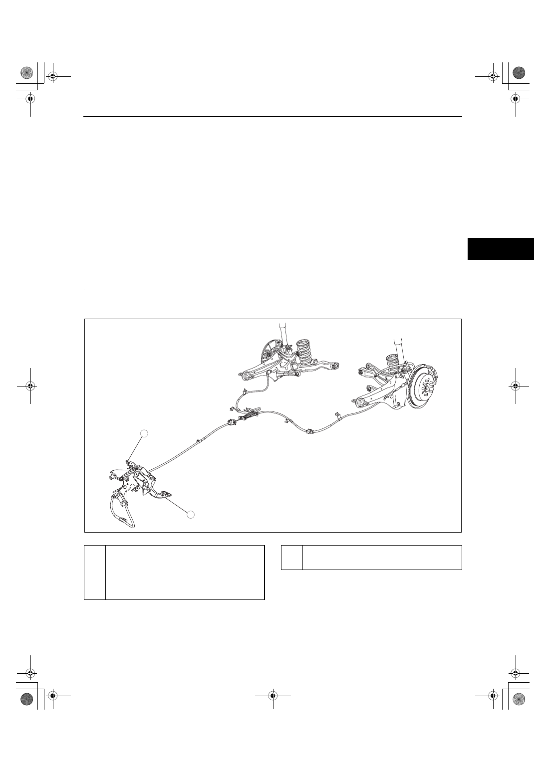
PARKING BRAKE SYSTEM LOCATION INDEX
id041200800100
.
End Of Sie
WM: PARKING BRAKE
2
1
acxuuw00001756
1
Parking brake (pedal type)
(See 04-12-2 PARKING BRAKE INSPECTION.)
(See 04-12-2 PARKING BRAKE ADJUSTMENT.)
(See 04-12-3 PARKING BRAKE REMOVAL/
INSTALLATION[2WD].)
(See 04-12-8 PARKING BRAKE REMOVAL/
INSTALLATION[AWD].)
2
Parking brake switch
(See 04-12-13 PARKING BRAKE SWITCH
INSPECTION.)
1871-1U-06B(04-12).fm 1 ページ 2006年3月15日 水曜日 午前11時15分