Mazda CX 7. Manual - part 212


  Index      Mazda     Mazda CX 7 - service repair manual 2007 year


Search            


Content   ..  210  211  212  213   ..


Mazda CX 7. Manual - part 212


CONVENTIONAL BRAKE SYSTEM 

04-11–19

04-11

Piston Disassembly Note
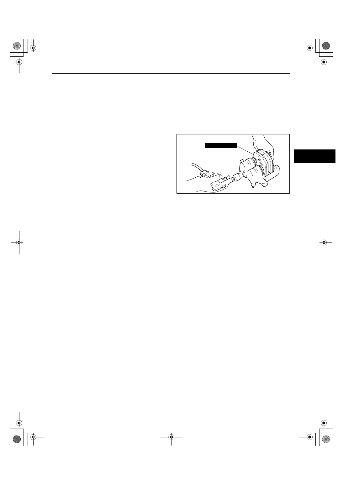
Warning

• When compressed air is blown into the caliper body, injury to a finger or other part from pinching 

could result from the piston springing up. When blowing in compressed air, do not place your 
fingers between the piston and caliper body when performing the work.

Caution

• The piston could be damaged if blown out with great force. Blow the compressed air slowly to 

prevent the piston from suddenly popping out.

1. Place the SST in the caliper, then blow 

compressed air through the hole to force the 
piston out of the caliper.

End Of Sie

WM: REAR BRAKE (DISC)

REAR BRAKE (DISC) INSPECTION

id041100800400

Brake Judder Repair Hint
Description
Brake judder concern has the following three characteristics:

Steering wheel vibration
Steering wheel vibrates in the direction of its rotation. This characteristic is most noticeable when applying brakes 
at a vehicle speed of 100— 140 km/h {62— 87 mph}.

Floor vibration
When applying brakes, the vehicle body shakes back and forth. The seriousness of shake is not influenced by 
vehicle speed.

Brake pedal vibration
When applying brakes, a pulsating force tries to push the brake pad back. The pulsation is transmitted to the brake 
pedal.
The following are the main possible causes of brake judder:

Due to an excessive runout (side-to-side wobble) of disc plate, the thickness of disc plate is uneven.
If the runout is more than 0.05 mm {0.002 in} at the position 10 mm {0.39 in} from the disc plate edge, uneven 
wear occurs on the disc plate because of uneven pad/plate contact.
If the runout is less than 0.05 mm {0.002 in}, uneven wear does not occur.

The disc plate is deformed by heat.
Repeated panic braking may raise the temperature in some portions of disc plate by approx. 1,000 

°C {1,832 °F}

This results in deformed disc plate.

Due to corrosion, the thickness and friction coefficient of disc plate change.
If a vehicle is parked under damp conditions for a long time, corrosion occurs on the friction surface of disc plate.
The thickness of corrosion is uneven and sometimes appears like a wave pattern, which changes the friction 
coefficient and causes a reaction force.

49 T033  001A

acxuuw00001887

1871-1U-06B(04-11).fm  19 ページ  2006年3月15日 水曜日 午前11時13分

CONVENTIONAL BRAKE SYSTEM 

04-11–20

Inspection and repair procedure

Lateral runout inspection

1. To secure the disc plate and the hub, tighten the hub nuts upside down or insert a washer (thickness 10 mm 

{0.39 in} with an inner diameter more than 12 mm {0.47 in}) between the hub bolt and the hub nut.

Note

• The component parts of the SST (49 B017 001 or 49 G019 003) can be used as a suitable washer.

2. After tightening all the hub nuts to the same torque, put the dial gauge on the friction surface of disc plate 10 

mm {0.39 in} from the disc plate edge.

3. Rotate the disc plate one time and measure the runout.

Rear disc plate runout limit

0.05 mm {0.002 in}

Occurs

Does not
occur

Confirm customer

,

s complaint

Less than
0.05 mm
{0.002 in}

Less than 0.015 mm {0.0005 in}

On-the-car type lathe (less than
0.015 mm {0.0005 in}).

More than 0.015 mm {0.0005 in}

More than 0.05 mm {0.002 in}

More than
0.05 mm
{0.002 in}

Less than 
0.05 mm
{0.002 in}

Perform lateral runout inspection.
(Refer to Lateral Runout Inspection.)

Verify whether brake
judder occurs or not.

Machine the disc plate using
on-the-car type lathe.

Remove disc plate and
reinstall in other phase.
Perform lateral runout
inspection again.

Perform thickness variation
inspection (Refer to the
following.)

Secure the disc plate by
tightening all hub nuts to the
same torque, and measure lateral
runout.

Work is completed.

Confirm customer's complaint again.

Work is completed.

acxuuw00001070

1871-1U-06B(04-11).fm  20 ページ  2006年3月15日 水曜日 午前11時13分

CONVENTIONAL BRAKE SYSTEM 

04-11–21

04-11

Thickness variation inspection

1. Clean the disc plate-to-pad friction surface using a brake cleaner.
2. Measure the points indicated in the illustration using a caliper (micrometer).
3. Subtract the minimum value from the maximum. 

• If the result is not within specification, machine the disc plate using a lathe.

Thickness variation limit

0.015 mm {0.0005 in}

Warning

• Do not exceed minimum disc plate 

thickness.

Disc Plate Thickness Inspection

Caution

• Excessive runout may result if the disc plate is removed from the vehicle then machined. Machine 

the disc plate while installed on the vehicle.

1. Measure the thickness of the disc plate.

• If the thickness is not within the specification, replace the disc plate.

Minimum rear disc plate thickness

16 mm {0.63 in}

Minimum rear disc plate thickness after machining using a brake lathe on-vehicle

16.8 mm {0.66 in}

Disc Pad Thickness Inspection

1. Jack up the rear of the vehicle and support it with safety stands.
2. Remove the wheels.
3. Verify the remaining thickness of the pads.

• Replace the pads as a set: right and left wheels, if either one is at or less than the minimum thickness.

Minimum rear disc pad thickness

2.0 mm {0.08 in}

End Of Sie

acxuuw00001385

acxuuw00001654

1871-1U-06B(04-11).fm  21 ページ  2006年3月15日 水曜日 午前11時13分

CONVENTIONAL BRAKE SYSTEM 

04-11–22

REAR BRAKE (DISC) REMOVAL/INSTALLATION

id041100800500

1. Remove in the order indicated in the table.
2. Install in the reverse order of removal.
3. After installation, add brake fluid, bleed the air, and inspect for fluid leakage. (See 04-11-3 AIR BLEEDING.)
4. After installation, do the following.

(1) Depress the brake pedal a few times. Then verify that the brakes do not drag.
(2) Inspect the parking brake pedal stroke. (See 04-12-2 PARKING BRAKE INSPECTION.)

.

GREASEGREASE

GREASEGREASE

13

12

14

8

9

3

2

1

7

10

4

5

6

A

A

R

R

R

R

SST

2

21.6—31.4 
{2.21—3.20,
 16.0—23.1}

21.6—29.4 
{2.21—2.99,
 16.0—21.6}

78.4—101.9 
{8.00—10.39,
 57.9—75.1}

4

5

11

GREASEGREASE

RUBBER GREASE

21.6—31.4 {2.21—3.20, 16.0—23.1}

9.8—14.7 N·m 
{100—149 kgf·cm,
 87—130 in·lbf}

N·m {kgf·m, ft·lbf}

acxuuw00001739

1

Brake hose

2

Bolt

3

Caliper
(See 04-11-24 Caliper Installation Note.)

4

Disc pad

5

Shim

6

Guide plate

7

Bolt

8

Mounting support

9

Slide pin

10

Bush

11

Dust boot

12

Plug

13

Screw
(See 04-11-23 Disc Plate, Screw Installation Note.)

14

Disc plate
(See 04-11-23 Disc Plate Removal Note.)
(See 04-11-23 Disc Plate, Screw Installation Note.)

1871-1U-06B(04-11).fm  22 ページ  2006年3月15日 水曜日 午前11時13分


Content   ..  210  211  212  213   ..