Mazda CX 7. Manual - part 186


  Index      Mazda     Mazda CX 7 - service repair manual 2007 year


Search            


Content   ..  184  185  186  187   ..


Mazda CX 7. Manual - part 186


DIFFERENTIAL 

03-14–5

03-14

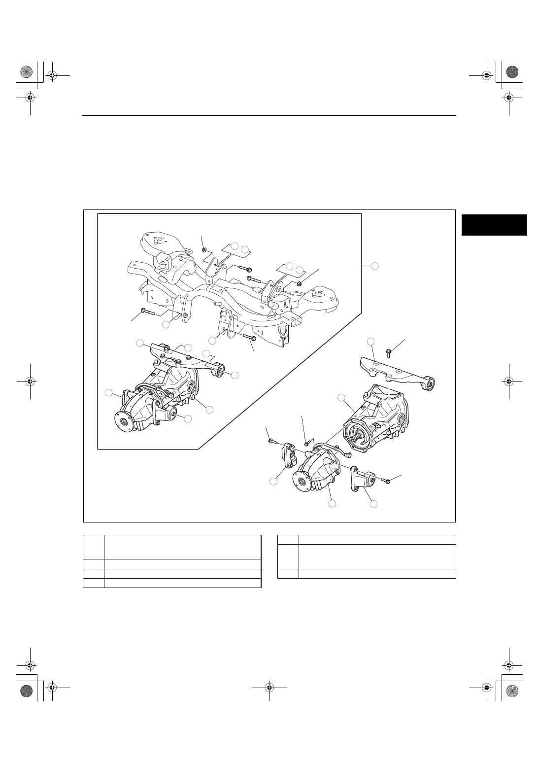
REAR DIFFERENTIAL REMOVAL/INSTALLATION

id031400800400

1. Drain the rear differential oil into a container.
2. Remove the main silencer and middle pipe. (See 01-15-2 EXHAUST SYSTEM REMOVAL/INSTALLATION[L3 

WITH TC].)

3. Remove the propeller shaft. (See 03-15-3 PROPELLER SHAFT REMOVAL/INSTALLATION.)
4. Remove the rear drive shaft. (See 03-13-20 REAR DRIVE SHAFT REMOVAL/INSTALLATION.)
5. Remove in the order indicated in the table.
6. Install in the reverse order of removal.
7. Add the specified rear differential oil. (See 03-14-2 DIFFERENTIAL OIL REPLACEMENT.)
8. Inspect the rear wheel alignment and adjust it if necessary. (See 02-11-4 REAR WHEEL ALIGNMENT.)

.

End Of Sie

2

6

4

7

3

1

5

D

C

F

D

E

B

C

A

F

E

B

A

N·m {kgf·m, ft·lbf}

43.1—60.8
{4.40—6.194,
31.8—44.8}

75.5—102
{7.70—10.4,
55.7—75.2}

75.5—102
{7.70—10.4,
55.7—75.2}

75.5—102
{7.70—10.4,
55.7—75.2}

75.5—102
{7.70—10.4,
55.7—75.2}

75.5—102
{7.70—10.4,
55.7—75.2}

75.5—102
{7.70—10.4,
55.7—75.2}

22.6—26.4
{2.31—2.69,
16.7—19.4}

acxuuw00001971

1

Rear crossmember and rear differential component
(See 02-14-20 REAR CROSSMEMBER REMOVAL/
INSTALLATION[AWD])

2

Rear differential component

3

Rear differential mounting rubber

4

Front differential mounting rubber (RH)

5

Front differential mounting rubber (LH)

6

Coupling component
(See 03-19-4 COUPLING COMPONENT 
REMOVAL/INSTALLATION)

7

Rear differential

1871-1U-06B(03-14).fm  5 ページ  2006年3月15日 水曜日 午前11時7分

DIFFERENTIAL 

03-14–6

REAR DIFFERENTIAL DISASSEMBLY

id031400800500

Warning

• The engine stand is equipped with a self-lock mechanism, however, if the rear differential is in a 

tilted condition, the self-lock mechanism could become inoperative. If the rear differential 
unexpectedly rotates it could cause injury, therefore do not maintain the rear differential in a tilted 
condition. When turning the rear differential, grasp the rotation handle firmly.

1. Disassemble in the order indicated in the table.

.

9

7

3

10

SST

SST

SST

SST

SST

6

18

14

13

12

8

5

5

4

3

1

2

19

17

15

15

16

11

20

24

24

23

23

21

21

22

22

6

25

acxuuw00001405

1

Differential oil temperature sensor

2

Rear cover
(See 03-14-7 Rear Cover Disassembly Note)

3

Bearing cap
(See 03-14-7 Bearing Cap Disassembly Note)

4

Rear differential component
(See 03-14-7 Rear Differential Component 
Disassembly Note) 

5

Side bearing outer race

6

Adjusting shim

7

Spacer

8

Locknut
(See 03-14-8 Locknut Disassembly Note)

9

Washer

10

Drive pinion
(See 03-14-8 Drive Pinion Disassembly Note)

11

Collapsible spacer

12

Bearing inner race (front bearing)

13

Bearing inner race (rear bearing)
(See 03-14-8 Bearing Inner Race (Rear Bearing) 
Disassembly Note)

14

Spacer

15

Bearing outer race
(See 03-14-8 Bearing Outer Race Disassembly 
Note)

16

Differential carrier

17

Ring gear
(See 03-14-9 Ring Gear Disassembly Note)

18

Knock pin

19

Pinion shaft

20

Pinion gear

21

Side gear

22

Thrust washer

1871-1U-06B(03-14).fm  6 ページ  2006年3月15日 水曜日 午前11時7分

DIFFERENTIAL 

03-14–7

03-14

Rear Cover Disassembly Note

1. Install the SSTs to the engine stand.

2. Install the rear differential to the SSTs.
3. Remove the rear cover using an oil seal cutter.

Bearing Cap Disassembly Note

1. Place alignment marks on the bearing cap and 

carrier.

Rear Differential Component Disassembly Note

1. Remove the rear differential component using the 

SSTs.

2. Mark or otherwise distinguish between the 

removed left and right adjusting shims, spacers 
and side bearing outer races so that they are not 
mixed up at the time of reassembly.

23

Side bearing inner race
(See 03-14-9 Side Bearing Inner Race Disassembly 
Note)

24

Oil seal

25

Gear case

49 L027 0A2

49 0107 680A

acxuuw00001406

49 L027 0A2

49 0107 680A

acxuuw00001407

MARK

acxuuw00001408

49 T032  317

49 T032  316

49 L027 004

acxuuw00001409

1871-1U-06B(03-14).fm  7 ページ  2006年3月15日 水曜日 午前11時7分

DIFFERENTIAL 

03-14–8

Locknut Disassembly Note

1. Remove the locknut using the SSTs.

Drive Pinion Disassembly Note

1. Remove the drive pinion by lightly tapping with a 

copper hammer.

Bearing Inner Race (Rear Bearing) Disassembly Note

1. Remove the bearing inner races (rear bearing) 

using the SST and a press.

Bearing Outer Race Disassembly Note

1. Remove the bearing outer races using the 2 

grooves in the carrier and alternately tapping the 
sides of the races with a brass bar.

49 L027 006

49 L027 007

acxuuw00001410

acxuuw00001411

49 H027 002

acxuuw00001412

acxuuw00001413

1871-1U-06B(03-14).fm  8 ページ  2006年3月15日 水曜日 午前11時7分


Content   ..  184  185  186  187   ..