Mazda CX 7. Manual - part 179


  Index      Mazda     Mazda CX 7 - service repair manual 2007 year


Search            


Content   ..  177  178  179  180   ..


Mazda CX 7. Manual - part 179


DRIVE SHAFT 

03-13–3

03-13

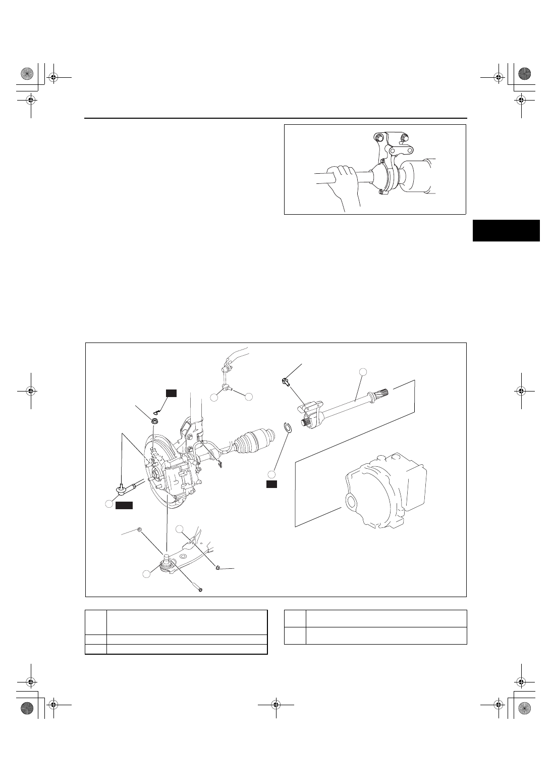
2. Turn the joint shaft by hand and verify that the 

bearing rotates smoothly and freely.

• Replace it as necessary.

End Of Sie

JOINT SHAFT REMOVAL/INSTALLATION[2WD]

id0313008009a3

Caution

• Performing the following procedures without first removing the ABS wheel-speed sensor may 

possibly cause an open circuit in the harness if it is pulled by mistake. Before performing the 
following procedures, remove the ABS wheel-speed sensor (axle side) and fix it to an appropriate 
place where the sensor will not be pulled by mistake while the vehicle is being serviced.

1. Remove the side cover and under cover.
2. Remove the front ABS wheel-speed sensor. (See 04-15-11 FRONT ABS WHEEL-SPEED SENSOR 

REMOVAL/INSTALLATION.)

3. Remove the crankshaft position (CKP) sensor. (See 01-40-42 CRANKSHAFT POSITION (CKP) SENSOR 

REMOVAL/INSTALLATION[L3 WITH TC].)

4. Remove in the order indicated in the table.
5. Install in the reverse order of removal.

.

acxuuw00001164

A

A

SST

R

R

5

4

3

1

2

47.0—59.0
{4.80—6.01,
34.7—43.5}

43.1—58.8
{4.40—5.99,
31.8—43.3}

42.3—60.1
{4.32—6.12,
31.2—44.3}

42—62
{4.3—6.3, 31—45}

N·m {kgf·m, ft·lbf}

acxuuw00001184

1

Tie-rod end ball joint
(See 02-13-10 FRONT CROSSMEMBER 
REMOVAL/INSTALLATION)

2

Stabilizer control link (lower side)

3

Lower arm ball joint

4

Joint shaft
(See 03-13-4 Joint Shaft Removal Note)

5

Clip
(See 03-13-4 Clip Installation Note)

1871-1U-06B(03-13).fm  3 ページ  2006年3月15日 水曜日 午前11時6分

DRIVE SHAFT 

03-13–4

Joint Shaft Removal Note

1. Separate the right side drive shaft from the joint 

shaft by tapping on a brass bar inserted between 
them.

2. Remove the bolts.
3. Pull the joint shaft straight out.

Caution

• The sharp edges of the joint shaft can 

slice or puncture the oil seal. Be careful 
when removing the joint shaft from the 
transaxle.

Clip Installation Note

1. Install a new clip onto the joint shaft with the opening facing upward. Ensure that the diameter of the clip does 

not exceed the specification on installation.

2. After installation, measure the outer diameter. If it 

exceeds the specification, repeat Step 1 using a 
new clip.

Clip outer diameter specification

34.0 mm {1.34 in} max.

End Of Sie

JOINT SHAFT REMOVAL/INSTALLATION[AWD]

id0313008009a5

Caution

• Performing the following procedures without first removing the ABS wheel-speed sensor may 

possibly cause an open circuit in the harness if it is pulled by mistake. Before performing the 
following procedures, remove the ABS wheel-speed sensor (axle side) and fix it to an appropriate 
place where the sensor will not be pulled by mistake while the vehicle is being serviced.

1. Remove the side cover and under cover.
2. Remove the front ABS wheel-speed sensor. (See 04-15-11 FRONT ABS WHEEL-SPEED SENSOR 

REMOVAL/INSTALLATION.)

3. Remove in the order indicated in the table.
4. Install in the reverse order of removal.

acxuuw00001185

OPENING

CLIP

OUTER 
DIAMETER

acxuuw00001186

1871-1U-06B(03-13).fm  4 ページ  2006年3月15日 水曜日 午前11時6分

DRIVE SHAFT 

03-13–5

03-13

.

Joint Shaft Removal Note

1. Separate the right side drive shaft from the joint 

shaft by tapping on a brass bar inserted between 
them.

2. Remove the bolts.
3. Pull the joint shaft straight out.

Caution

• The sharp edges of the joint shaft can 

slice or puncture the oil seal. Be careful 
when removing the joint shaft from the 
transaxle.

Clip Installation Note

1. Install a new clip onto the joint shaft with the opening facing upward. Ensure that the diameter of the clip does 

not exceed the specification on installation.

R

19—27 

  {1.93—2.75, 14.1—19.9}

 N·m {kgf·m,  ft·lbf}

A

A

SST

R

3

1

2

47.0—59.0
{4.80—6.01,
34.7—43.5}

43.1—58.8
{4.40—5.99,
31.8—43.3}

42.3—60.1
{4.32—6.12,
31.2—44.3}

5

4

acxuuw00001187

1

Tie-rod end ball joint
(See 02-13-10 FRONT CROSSMEMBER 
REMOVAL/INSTALLATION)

2

Stabilizer control link (lower side)

3

Lower arm ball joint

4

Joint shaft
(See 03-13-5 Joint Shaft Removal Note)

5

Clip
(See 03-13-5 Clip Installation Note)

acxuuw00001188

1871-1U-06B(03-13).fm  5 ページ  2006年3月15日 水曜日 午前11時6分

DRIVE SHAFT 

03-13–6

2. After installation, measure the outer diameter. If it 

exceeds the specification, repeat Step 1 using a 
new clip.

Outer diameter specification

34.0 mm {1.34 in} max.

End Of Sie

JOINT SHAFT DISASSEMBLY[2WD]

id0313008010a3

1. Disassemble in the order indicated in the table.

.

Dust Seal (Axle Side) Disassembly Note

1. Remove the dust seal using a flathead screwdriver.

Joint Shaft Disassembly Note

1. Remove the joint shaft using a press.

OPENING

CLIP

OUTER 
DIAMETER

acxuuw00001189

5

4

3

6

1

2

SST

SST

8

7

acxuuw00001302

1

Cover

2

Dust seal (axle side)
(See 03-13-6 Dust Seal (Axle Side) Disassembly 
Note)

3

Snap ring

4

Snap ring

5

Joint shaft
(See 03-13-6 Joint Shaft Disassembly Note)

6

Dust seal (differential side)
(See 03-13-7 Dust Seal (Differential Side) 
Disassembly Note)

7

Bearing
(See 03-13-7 Bearing Disassembly Note)

8

Bearing housing

ampjjw00003305

1871-1U-06B(03-13).fm  6 ページ  2006年3月15日 水曜日 午前11時6分


Content   ..  177  178  179  180   ..