Mazda CX 7. Manual - part 163


  Index      Mazda     Mazda CX 7 - service repair manual 2007 year


Search            


Content   ..  161  162  163  164   ..


Mazda CX 7. Manual - part 163


FRONT SUSPENSION 

02-13–7

02-13

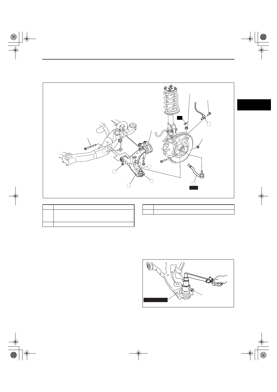
FRONT LOWER ARM REMOVAL/INSTALLATION

id021300800600

1. Remove the under cover.
2. Remove in the order indicated in the table.
3. Install in the reverse order of removal.

.

End Of Sie

FRONT LOWER ARM INSPECTION

id021300800700

1. Remove the lower arm from the vehicle.
2. Inspect the arm for bending or damage, and the ball joint for excessive looseness.

• If there is any malfunction, replace the lower arm.

3. Rotate the ball joint stud 5 times. Install the SST 

and M6 bolt (bolt length (measured from below 
the head): 20 mm {0.79 in}) to the ball joint stud, 
measure the rotational torque using a torque 
wrench.

• If not within the specification, replace the 

lower arm.

Front lower arm rotational torque

1.4— 2.0 N·m {15— 20 kgf·cm, 13— 17 in·lbf} 

End Of Sie

WM: FRONT STABILIZER

1

5

3

A

A

2

R

4

SST

85.7—100.0
{8.74—10.19, 
63.21—73.75}

85.7—100.0
{8.74—10.19, 
63.21—73.75}

47.0—59.0
{4.80—6.01, 
34.7—43.5}

43.1—58.8
{4.40—5.99, 
31.8—43.3}

43.1—60.8
{4.32—6.12, 
31.2—44.3}

7.8—10.8 N·m 
{80—110 kgf·cm, 
69.1—95.5 in·lbf}

N·m {kgf·m, ft·lbf}

acxuuw00001260

1

ABS wheel speed sensor

2

Tie-rod end ball joint
 (See 02-13-10 FRONT CROSSMEMBER 
REMOVAL/INSTALLATION.)

3

Stabilizer control link lower nut

4

Front lower arm ball joint

5

Front lower arm

49 FT01 389

M6 BOLT

 (BOLT LENGTH 
(MEASURED FROM 
BELOW THE HEAD): 
20 mm {0.79 in})

acxuuw00001103

1871-1U-06B(02-13).fm  7 ページ  2006年3月15日 水曜日 午前11時0分

FRONT SUSPENSION 

02-13–8

FRONT STABILIZER REMOVAL/INSTALLATION

id021300800400

1. Remove the side cover and under cover.
2. Drain the power steering fluid. (See 06-14-3 POWER STEERING FLUID INSPECTION.)
3. Remove the transverse member. (See 02-13-14 TRANSVERSE MEMBER REMOVAL/INSTALLATION.)
4. Remove the front crossmember component. (See 02-13-10 FRONT CROSSMEMBER REMOVAL/

INSTALLATION.)

5. Remove in the order indicated in the table.
6. Install in the reverse order of removal.

.

Front Stabilizer Installation Note

1. Install the stabilizer bar so that the identification 

mark is on the left side of the vehicle.

GREASEGREASE

2

5

3

4

1

N·m {kgf·m, ft·lbf}

42.3—60.1 
{4.32—6.12, 
31.2—44.3}

42.3—60.1 
{4.32—6.12, 
31.2—44.3}

43.1—60.8 
{4.40—6.19, 
31.8—44.8}

RUBBER 
GREASE

acxuuw00001098

1

Front stabilizer component

2

Front stabilizer control link

3

Stabilizer bracket
 (See 02-13-9 Stabilizer Bracket Installation Note)

4

Stabilizer bushing
(See 02-13-9 Stabilizer Bushing Installation Note)

5

Front stabilizer
(See 02-13-8 Front Stabilizer Installation Note)

FRONT

IDENTIFICATION 
MARK

POSITIONING PLATE

acxuuw00001099

1871-1U-06B(02-13).fm  8 ページ  2006年3月15日 水曜日 午前11時0分

FRONT SUSPENSION 

02-13–9

02-13

Stabilizer Bushing Installation Note

1. Align the outer side of the positioning plate with 

the stabilizer bushing.

Stabilizer Bracket Installation Note

1. Install the stabilizer bracket so that the arrow is 

pointed to the front.

End Of Sie

WM: STABILIZER CONTROL LINK (FRONT/REAR)

STABILIZER CONTROL LINK INSPECTION

id021300800500

1. Remove the stabilizer control link from the vehicle. (See 02-13-8 FRONT STABILIZER REMOVAL/

INSTALLATION.)

2. Inspect for bending and damage.
3. Measure the ball joint starting torque.

(1) Rock the ball joint stud side to side 10 times.
(2) Rotate the ball joint stud 10 times.
(3) Measure the starting torque using a suitable 

allen socket and a torque wrench.

Front stabilizer control link ball joint starting 

torque

0.2— 0.9 N·m {2.1— 9.1 kgf·cm, 1.8— 7.9 

in·lbf}

End Of Sie

WM: FRONT CROSSMEMBER

FRONT

IDENTIFICATION 
MARK

POSITIONING PLATE

STABILIZER 
BUSHING

acxuuw00001100

ampjjw00000547

ampjjw00002979

1871-1U-06B(02-13).fm  9 ページ  2006年3月15日 水曜日 午前11時0分

FRONT SUSPENSION 

02-13–10

FRONT CROSSMEMBER REMOVAL/INSTALLATION

id021300801000

1. Remove the side cover and under cover.
2. Drain the power steering fluid. (See 06-14-3 POWER STEERING FLUID INSPECTION.)
3. Remove the transverse member. (See 02-13-14 TRANSVERSE MEMBER REMOVAL/INSTALLATION.)
4. Remove the intermediate shaft installation bolt, and disconnect the steering shaft. (See 06-14-6 STEERING 

WHEEL AND COLUMN REMOVAL/INSTALLATION.)

5. Remove in the order indicated in the table.
6. Install in the reverse order of removal.
7. When replace the front crossmember, inspect the front wheel alignment and adjust it if necessary. (See 02-11-

2 FRONT WHEEL ALIGNMENT.)

.

SST

N·m {kgf·m, ft·lbf}

7.8—10.8 N·m
{80—110 kgf·cm,
70.0—95.5 in·lbf}

119.6—154.8 
{12.20—15.78, 
88.3—114.1}

93.1—116.6
{9.50—11.88, 
68.7—85.9}

85.7—100
{8.74—10.1, 
63.3—73.3}

85.7—100
{8.74—10.1, 
63.3—73.3}

47—59
{4.8—6.0, 
35—43}

42.3—60.1
{4.32—6.12, 
31.2—44.3}

42.3—60.1
{4.32—6.12, 
31.2—44.3}

43.1—60.8
{4.40—6.19, 
31.8—44.8}

43.1—58.8
{4.40—5.99, 
31.8—43.3}

119.6—154.8 
{12.20—15.78, 
88.3—114.1}

29.4—44.1
{3.00—4.49, 
21.7—32.5}

74.4—104.8
{7.59—10.68, 
54.88—77.29}

10

6

3

1

A

B

12

8

C

5

2

A

7

11

9

D

D

4

B

C

R

7.8—10.8

 N·m 

{80—110 kgf·cm,
 70—95 in·lbf}

R

acxuuw00001942

1

ABS wheel speed sensor

2

Tie-rod end ball joint
(See 02-13-11 Tie-rod End Ball Joint Removal Note)

3

Front lower arm ball joint

4

Stabilizer control link lower side nut

5

Steering gear and linkage, front stabilizer, front 
lower arm and front crossmember component
(See 02-13-11 Steering Gear And Linkage, Front 
Stabilizer, Front Lower Arm And Front 
Crossmember Component Removal Note)
(See 02-13-13 Steering Gear And Linkage, Front 
Stabilizer, Front Lower Arm And Front 
Crossmember Component Installation Note)

6

No. 1 engine mount

7

Front stabilizer

8

Steering gear and linkage

9

Front lower arm

10

Front crossmember

11

Front crossmember mounting rubber (front)
(See 02-13-12 Front Crossmember Mounting 
Rubber (front) Installation Note)

12

Front crossmember mounting rubber (rear)
(See 02-13-12 Front Crossmember Mounting 
Rubber (rear) Installation Note)

1871-1U-06B(02-13).fm  10 ページ  2006年3月15日 水曜日 午前11時0分


Content   ..  161  162  163  164   ..