Mazda CX 7. Manual - part 161
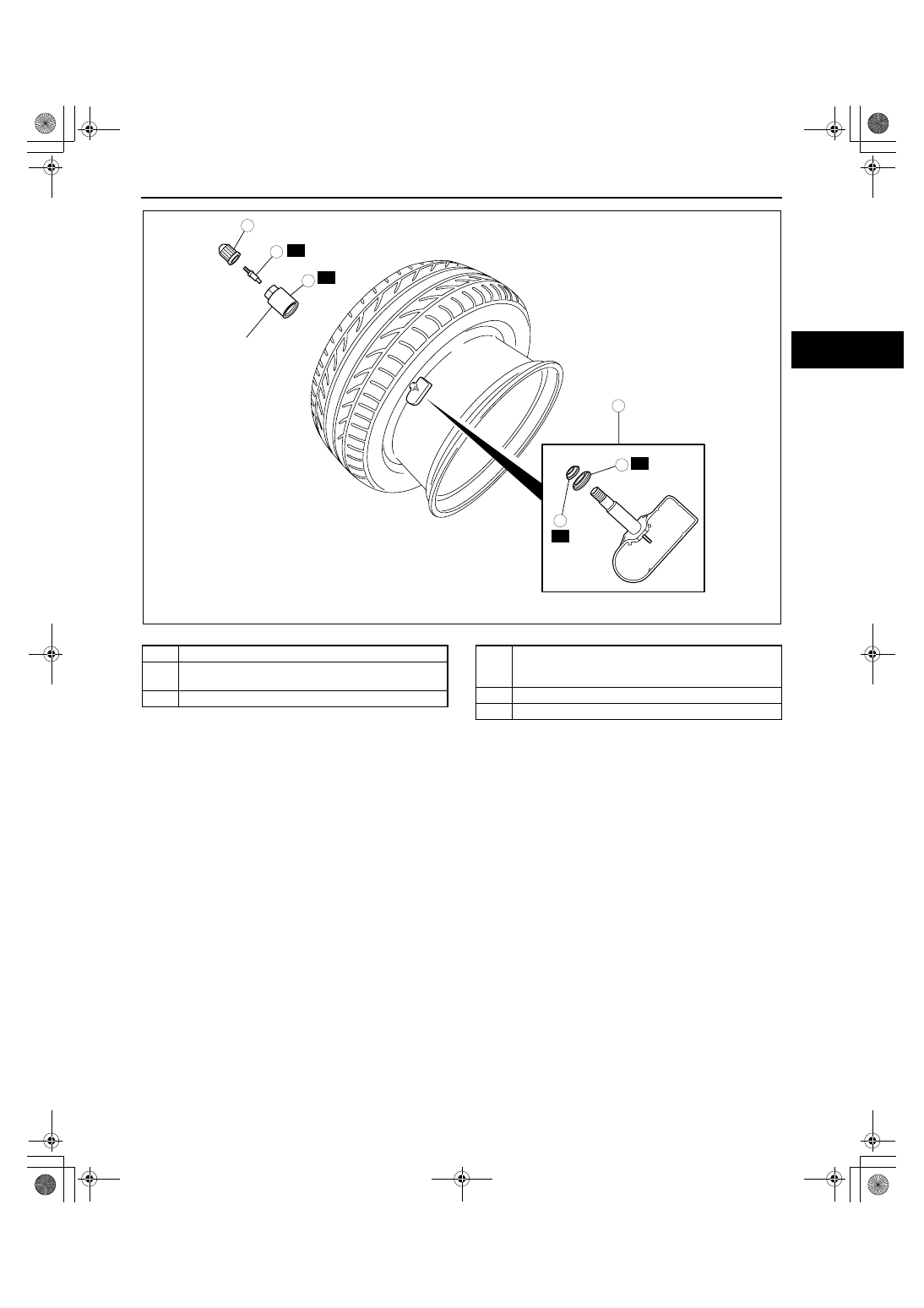
WHEEL AND TIRES
02-12–5
02-12
.
Valve Core Removal Note
1. Remove the valve core of the wheel unit, and bleed the air from the tire.
Wheel Unit Removal Note
1. Push the tire valve completely into the tire.
Caution
• Breaking the tire bead with the wheel unit installed normally could damage the unit. Be sure to
always push the wheel unit so that it is completely inside the tire to prevent any damage.
2. Position the shoe (bead breaker) of the tire changer 10— 20 mm {0.40— 0.78 in} from the outer edge of the
wheel, and break both tire beads.
3. Remove the bead from one side of the wheel.
4. Remove the wheel unit.
R
R
R
R
7.5—8.5
{77—86, 67—75}
1
2
3
4
N·m {kgf·cm, in·lbf}
6
5
acxuuw00001040
1
Valve cap
2
Valve core
(See 02-12-5 Valve Core Removal Note.)
3
Valve nut and washer
4
Wheel unit
(See 02-12-5 Wheel Unit Removal Note.)
(See 02-12-6 Wheel Unit Installation Note.)
5
Seal washer
6
Seal
1871-1U-06B(02-12).fm 5 ページ 2006年3月15日 水曜日 午前10時59分