Mazda CX 7. Manual - part 148
CONTROL SYSTEM [L3 WITH TC]
01-40–33
01-40
Circuit Open/Short Inspection
1. Disconnect the PCM connector. (See01-40-6 PCM REMOVAL/INSTALLATION[L3 WITH TC].)
2. Inspect the following wiring harnesses for an open or short circuit. (Continuity check)
Open circuit
• If there is no continuity, there is an open circuit. Repair or replace the wiring harness.
— Throttle body terminal A and PCM terminal 2AK
— Throttle body terminal B and PCM terminal 2AO
— Throttle body terminal C and PCM terminal 2AL
— Throttle body terminal D and PCM terminal 2AP
Short circuit
• If there is continuity, there is a short circuit. Repair or replace the wiring harness.
— Throttle body terminal A and power supply
— Throttle body terminal A and body ground
— Throttle body terminal B and body ground
— Throttle body terminal C and power supply
— Throttle body terminal C and body ground
— Throttle body terminal D and power supply
End Of Sie
WM: ACCELERATOR PEDAL POSITION SENSOR
ACCELERATOR PEDAL POSITION (APP) SENSOR INSPECTION[L3 WITH TC]
id014039803200
Note
• Before performing the following inspection, make sure to follow the procedure as indicated in the
troubleshooting flowchart. (See 00-00-3 HOW TO USE THIS MANUAL.)
Voltage Inspection
1. Turn the ignition switch to the ON position (Engine off).
2. Verify that the PCM terminal 1Y and 1AC change smoothly while throttle valve is gradually opened.
• If as verified, go to next step.
• If not as verified, perform the “Circuit Open/Short Inspection”.
— If there is no open or short circuit, replace the throttle body. (See01-13-5 INTAKE AIR SYSTEM
REMOVAL/INSTALLATION[L3 WITH TC].)
A
B
C
D
E
F
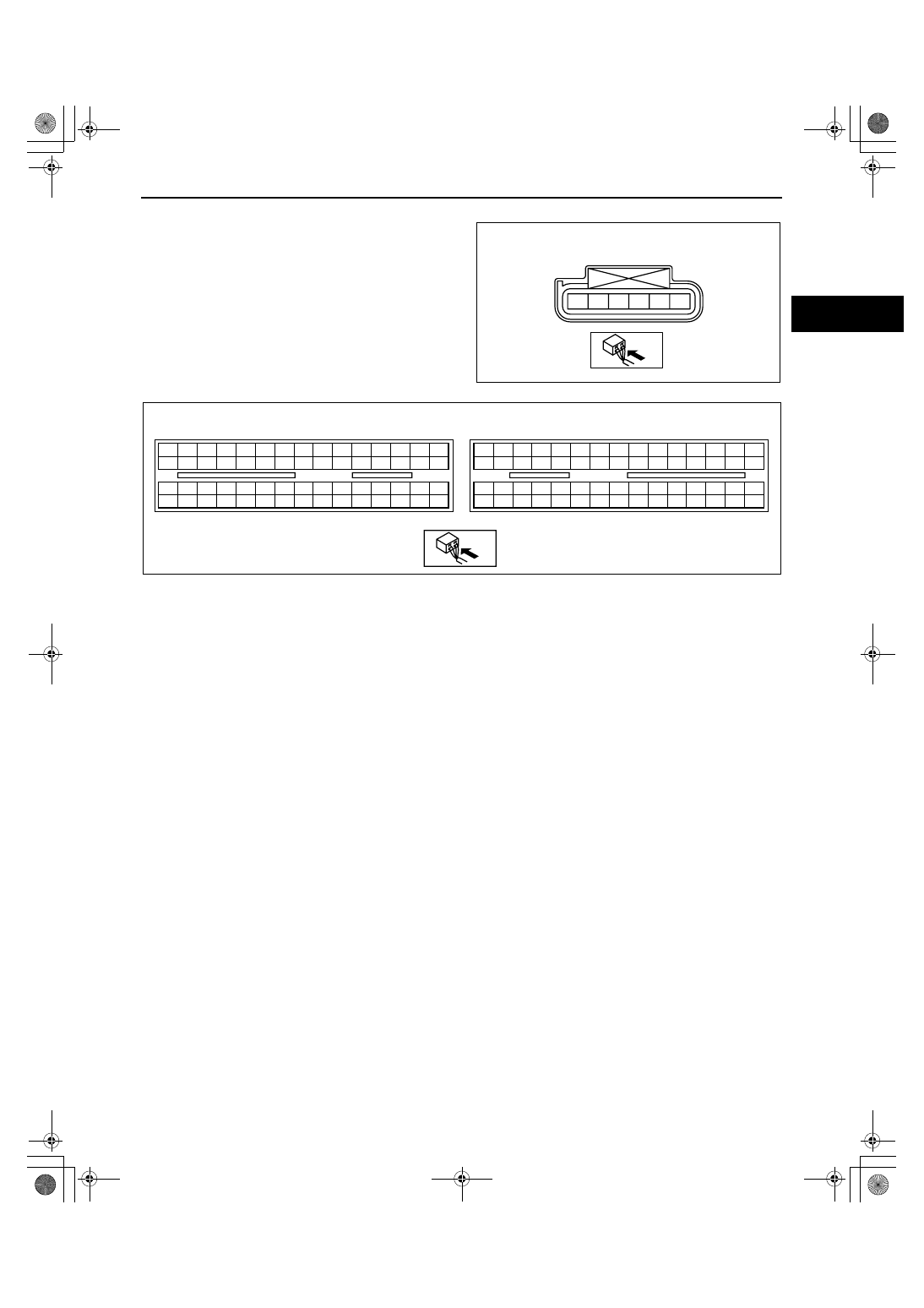
TP SENSOR
WIRING HARNESS SIDE CONNECTOR
acxuuw00000110
2BE 2BA 2AW 2AS 2AO 2AK 2AG 2AC 2Y 2U 2Q 2M
2E
2A
2I
2BH 2BD 2AZ 2AV 2AR 2AN 2AJ 2AF 2AB 2X 2T 2P
2H
2D
2L
2BG 2BC 2AY 2AU 2AQ 2AM 2AI 2AE 2AA 2W 2S 2O
2G
2C
2K
2BF 2BB 2AX 2AT 2AP 2AL 2AH 2AD 2Z
2V 2R 2N
2F
2B
2J
1BE 1BA 1AW 1AS 1AO 1AK 1AG 1AC 1Y 1U 1Q 1M
1E
1A
1I
1BH 1BD 1AZ 1AV 1AR 1AN 1AJ 1AF 1AB 1X
1T
1P
1H
1D
1L
1BG 1BC 1AY 1AU 1AQ 1AM 1AI 1AE 1AA 1W 1S 1O
1G
1C
1K
1BF 1BB 1AX 1AT 1AP 1AL 1AH 1AD 1Z
1V
1R 1N
1F
1B
1J
PCM
WIRING HARNESS-SIDE CONNECTOR
acxuuw00000108
1871-1U-06B(01-40).fm 33 ページ 2006年3月15日 水曜日 午前10時53分