Mazda CX 7. Manual - part 146


  Index      Mazda     Mazda CX 7 - service repair manual 2007 year


Search            


Content   ..  144  145  146  147   ..


Mazda CX 7. Manual - part 146


CONTROL SYSTEM [L3 WITH TC]

01-40–25

01-40

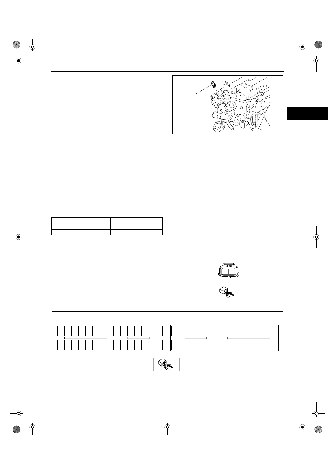
7. Remove the ECT sensor.
8. Install in the reverse order of removal.

Tightening torque

10— 14 N·m {102— 142 kgf·cm, 89— 123 

in·lbf}

9. Refill the engine coolant. (See01-12-2 COOLING 

SYSTEM SERVICE WARNINGS[L3 WITH TC].)

End Of Sie

ENGINE COOLANT TEMPERATURE (ECT) SENSOR INSPECTION[L3 WITH TC]

id014039802000

Note

• Before performing the following inspection, make sure to follow the procedure as indicated in the 

troubleshooting flowchart. (See 00-00-3 HOW TO USE THIS MANUAL.)

ECT Sensor Resistance Inspection

1. Drain the engine coolant. (See01-12-2 COOLING SYSTEM SERVICE WARNINGS[L3 WITH TC].)
2. Remove the ECT sensor (located above the starter).
3. Place the ECT sensor in water with a thermometer, and heat the water gradually.
4. Measure the resistance between the ECT sensor terminals A and B using a tester.

• If not as specified, replace the ECT sensor.

• If the ECT sensor is normal, but PID value is out of specification, perform the “Circuit Open/Short 

Inspection”.

Specification

Circuit Open/Short Inspection

1. Disconnect the PCM connector. (See01-40-6 PCM REMOVAL/INSTALLATION[L3 WITH TC].)
2. Inspect the following wiring harnesses for an open or short circuit. (Continuity check)

ECT SENSOR

acxuuw00000091

Water temperature (

°C {°F})

Resistance (kilohm)

20 {68}

35.48— 39.20

80 {176}

3.65— 4.02

A

B

ECT SENSOR 

WIRING HARNESS SIDE CONNECTOR

acxuuw00000092

2BE 2BA 2AW 2AS 2AO 2AK 2AG 2AC 2Y 2U 2Q 2M

2E

2A

2I

2BH 2BD 2AZ 2AV 2AR 2AN 2AJ 2AF 2AB 2X 2T 2P

2H

2D

2L

2BG 2BC 2AY 2AU 2AQ 2AM 2AI 2AE 2AA 2W 2S 2O

2G

2C

2K

2BF 2BB 2AX 2AT 2AP 2AL 2AH 2AD 2Z

2V 2R 2N

2F

2B

2J

1BE 1BA 1AW 1AS 1AO 1AK 1AG 1AC 1Y 1U 1Q 1M

1E

1A

1I

1BH 1BD 1AZ 1AV 1AR 1AN 1AJ 1AF 1AB 1X

1T

1P

1H

1D

1L

1BG 1BC 1AY 1AU 1AQ 1AM 1AI 1AE 1AA 1W 1S 1O

1G

1C

1K

1BF 1BB 1AX 1AT 1AP 1AL 1AH 1AD 1Z

1V

1R 1N

1F

1B

1J

PCM

WIRING HARNESS-SIDE CONNECTOR

acxuuw00000093

1871-1U-06B(01-40).fm  25 ページ  2006年3月15日 水曜日 午前10時53分

CONTROL SYSTEM [L3 WITH TC]

01-40–26

Open circuit

• If there is no continuity, there is an open circuit. Repair or replace the wiring harness.

— ECT sensor terminal A and PCM terminal 2AH

— ECT sensor terminal B and PCM terminal 2AY

Short circuit

• If there is continuity, there is a short circuit. Repair or replace the wiring harness.

— ECT sensor terminal A and power supply

— ECT sensor terminal A and body ground

— ECT sensor terminal B and power supply

End Of Sie

WM: MASS AIR FLOW SENSOR

MASS AIR FLOW (MAF) SENSOR INSPECTION[L3 WITH TC]

id014039800700

Visual Inspection

Note

• Before performing the following inspection, make sure to follow the procedure as indicated in the 

troubleshooting flowchart. (See 00-00-3 HOW TO USE THIS MANUAL.)

1. Visually inspect for the following on the MAF sensor. (See01-13-5 INTAKE AIR SYSTEM REMOVAL/

INSTALLATION[L3 WITH TC].)

• Damage

• Cracks

• Bent terminals

• Terminal rust

— If any of the above are found, replace the MAF/IAT sensor.

— If the monitor item status/specification (reference) is not within the specification even though there is no 

malfunction, perform the "Circuit Open/Short Inspection". 

Voltage Inspection 

1. Remove the MAF/IAT sensor without disconnect the MAF/IAT sensor connector. 
2. Turn the ignition switch to the ON position. 
3. As the air gradually approaches the MAF detection part of the MAF/IAT sensor, verify that the voltage at PCM 

terminal 1AK (M-MDS PID: MAF) varies. 

• If it cannot be verified even though the related harnesses have no malfunction, replace the MAF/IAT sensor. 

Circuit Open/Short Inspection

A

B

C

D

E

MAF/IAT SENSOR

WIRING HARNESS SIDE CONNECTOR

acxuuw00000076

FUSE BOX

(MAIN RELAY)

A

E

B

D

FRONT

acxuuw00000538

1871-1U-06B(01-40).fm  26 ページ  2006年3月15日 水曜日 午前10時53分

CONTROL SYSTEM [L3 WITH TC]

01-40–27

01-40

1. Disconnect the PCM connector. (See01-40-6 PCM REMOVAL/INSTALLATION[L3 WITH TC].)
2. Disconnect the MAF/IAT sensor connector.
3. Inspect the following wiring harnesses for an open or short circuit. (Continuity check)

Open circuit

• If there is no continuity, there is an open circuit. Repair or replace the wiring harness.

— MAF/IAT sensor terminal A and main relay terminal E

— MAF/IAT sensor terminal B and PCM terminal 1P

— MAF/IAT sensor terminal C and PCM terminal 1AK

Short circuit

• If there is continuity, there is a short circuit. Repair or replace the wiring harness.

— MAF/IAT sensor terminal A and body ground

— MAF/IAT sensor terminal B and power supply

— MAF/IAT sensor terminal C and power supply

— MAF/IAT sensor terminal C and body ground

End Of Sie

WM: INTAKE AIR TEMPERATURE SENSOR

INTAKE AIR TEMPERATURE (IAT) SENSOR INSPECTION[L3 WITH TC]

id014039802200

Resistance Inspection

Note

• Before performing the following inspection, make sure to follow the procedure as indicated in the 

troubleshooting flowchart. (See 00-00-3 HOW TO USE THIS MANUAL.)

1. Disconnect the MAF/IAT sensor.
2. Measure the resistance between the MAF/IAT 

sensor terminals D and E using a tester.

• If not as specified, replace the MAF/IAT 

sensor. (See01-13-5 INTAKE AIR SYSTEM 
REMOVAL/INSTALLATION[L3 WITH TC].)

• If the MAF/IAT sensor is normal, but the PID 

is out of specification, perform the “Circuit 
Open/Short Inspection”.

Specification

2BE 2BA 2AW 2AS 2AO 2AK 2AG 2AC 2Y 2U 2Q 2M

2E

2A

2I

2BH 2BD 2AZ 2AV 2AR 2AN 2AJ 2AF 2AB 2X 2T 2P

2H

2D

2L

2BG 2BC 2AY 2AU 2AQ 2AM 2AI 2AE 2AA 2W 2S 2O

2G

2C

2K

2BF 2BB 2AX 2AT 2AP 2AL 2AH 2AD 2Z

2V 2R 2N

2F

2B

2J

1BE 1BA 1AW 1AS 1AO 1AK 1AG 1AC 1Y 1U 1Q 1M

1E

1A

1I

1BH 1BD 1AZ 1AV 1AR 1AN 1AJ 1AF 1AB 1X

1T

1P

1H

1D

1L

1BG 1BC 1AY 1AU 1AQ 1AM 1AI 1AE 1AA 1W 1S 1O

1G

1C

1K

1BF 1BB 1AX 1AT 1AP 1AL 1AH 1AD 1Z

1V

1R 1N

1F

1B

1J

PCM

WIRING HARNESS-SIDE CONNECTOR

acxuuw00000078

Ambient temperature (

°C {°F})

Resistance (kilohm)

20 {68}

2.21— 2.69

60 {140}

0.493— 0.667

A

B

C

D

E

acxuuw00000096

1871-1U-06B(01-40).fm  27 ページ  2006年3月15日 水曜日 午前10時53分

CONTROL SYSTEM [L3 WITH TC]

01-40–28

Circuit Open/Short Inspection

1. Disconnect the PCM connector. (See01-40-6 PCM REMOVAL/INSTALLATION[L3 WITH TC].)
2. Inspect the following wiring harnesses for an open or short circuit. (Continuity check)

Open circuit

• If there is no continuity, there is an open circuit. Repair or replace the wiring harness.

— MAF/IAT sensor terminal D and PCM terminal 1M

— MAF/IAT sensor terminal E and PCM terminal 1AR

Short circuit

• If there is continuity, there is a short circuit. Repair or replace the wiring harness.

— MAF/IAT sensor terminal E and power supply

— MAF/IAT sensor terminal D and power supply

— MAF/IAT sensor terminal D and body ground

End Of Sie

WM: MANIFOLD ABSOLUTE PRESSURE SENSOR

A

B

C

D

E

MAF/IAT SENSOR

WIRING HARNESS SIDE CONNECTOR

acxuuw00000097

2BE 2BA 2AW 2AS 2AO 2AK 2AG 2AC 2Y 2U 2Q 2M

2E

2A

2I

2BH 2BD 2AZ 2AV 2AR 2AN 2AJ 2AF 2AB 2X 2T 2P

2H

2D

2L

2BG 2BC 2AY 2AU 2AQ 2AM 2AI 2AE 2AA 2W 2S 2O

2G

2C

2K

2BF 2BB 2AX 2AT 2AP 2AL 2AH 2AD 2Z

2V 2R 2N

2F

2B

2J

1BE 1BA 1AW 1AS 1AO 1AK 1AG 1AC 1Y 1U 1Q 1M

1E

1A

1I

1BH 1BD 1AZ 1AV 1AR 1AN 1AJ 1AF 1AB 1X

1T

1P

1H

1D

1L

1BG 1BC 1AY 1AU 1AQ 1AM 1AI 1AE 1AA 1W 1S 1O

1G

1C

1K

1BF 1BB 1AX 1AT 1AP 1AL 1AH 1AD 1Z

1V

1R 1N

1F

1B

1J

PCM

WIRING HARNESS-SIDE CONNECTOR

acxuuw00000098

1871-1U-06B(01-40).fm  28 ページ  2006年3月15日 水曜日 午前10時53分


Content   ..  144  145  146  147   ..