Mazda CX 7. Manual - part 143


  Index      Mazda     Mazda CX 7 - service repair manual 2007 year


Search            


Content   ..  141  142  143  144   ..


Mazda CX 7. Manual - part 143


CONTROL SYSTEM [L3 WITH TC]

01-40–13

01-40

Inspection Using An Oscilloscope (Reference)
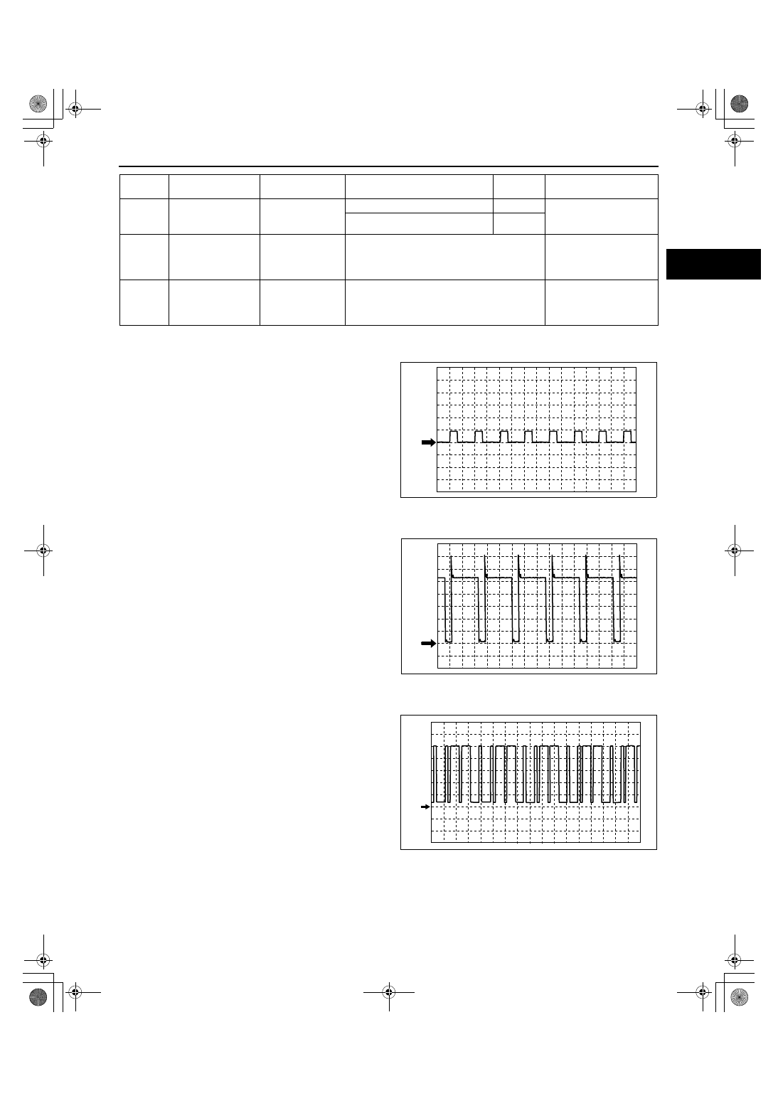
Fan control module (No.1) signal
PCM terminals

• 1AE (+)— body ground (–)

Oscilloscope setting

• 5 V/DIV (Y), 20 ms/DIV (X), DC range

Vehicle condition

• Idle after warm up (no load, P/S off, A/C off)

HO2S (front) heater control signal
PCM terminals

• 2C (+)— body ground (–)

Oscilloscope setting

• 2 V/DIV (Y), 20 ms/DIV (X), DC range

Vehicle condition

• Idle after warm up (no load, P/S off, A/C off)

CMP sensor signal
PCM terminals

• 2S (+)— body ground (–)

Oscilloscope setting

• 2 V/DIV (Y), 100 ms/DIV (X), DC range

Vehicle condition

• Idle after warm up (no load, P/S off, A/C off)

2BF

Fuel injector power 
supply 2

Fuel Injector relay

Ignition switch off

Below 1.0

• Fuel Injector relay

• Related wiring 

harness

Ignition switch to the ON position

B+

2BG

Fuel injection
(+)(#1, #4)

Fuel injector 
(No.1,No.4)

• Inspect using the wave profile.

(See01-40-6 PCM inspection 
preparation.)

• Fuel injector No.1, 

No.4

• Related wiring 

harness

2BH

Fuel injection
(+)(#2, #3)

Fuel injector
(No.2, No.3)

• Inspect using the wave profile.

(See01-40-6 PCM inspection 
preparation.)

• Fuel injector No.2, 

No.3

• Related wiring 

harness

Terminal

Signal

Connected to

Test condition

Voltage 

(V)

Inspection item

0 V

acxuuw00000274

0 V

acxuuw00000275

0 V

acxuuw00000127

1871-1U-06B(01-40).fm  13 ページ  2006年3月15日 水曜日 午前10時53分

CONTROL SYSTEM [L3 WITH TC]

01-40–14

CKP sensor signal
PCM terminals

• 2W (+)— body ground (–)

Oscilloscope setting

• 2 V/DIV (Y), 5 ms/DIV (X), DC range

Vehicle condition

• Idle after warm up (no load, P/S off, A/C off)

Wastegate control solenoid valve signal
PCM terminals

• 2AA (+)— body ground (–)

Oscilloscope setting

• 20 V/DIV (Y), 20 ms/DIV (X), DC range

Vehicle condition

• Ignition switch to the ON position

Purge control signal
PCM terminals

• 2AB (+)— body ground (–)

Oscilloscope setting

• 10 V/DIV (Y), 20 ms/DIV (X), DC range

Vehicle condition

• Engine speed is 2,000 rpm

OCV signal
PCM terminals

• 2AF (+)— body ground (–)

Oscilloscope setting

• 2.5 V/DIV (Y), 1 ms/DIV (X), DC range

Vehicle condition

• Idle after warm up (no load, P/S off, A/C off)

ov

acxuuw00000128

0 V

acxuuw00002325

0 V

ampjjw00001527

ov

acxuuw00000129

1871-1U-06B(01-40).fm  14 ページ  2006年3月15日 水曜日 午前10時53分

CONTROL SYSTEM [L3 WITH TC]

01-40–15

01-40

Generator field coil control signal
PCM terminals

• 2AI (+)— body ground (–)

Oscilloscope setting

• 0.5 V/DIV (Y), 2 ms/DIV (X), DC range

Vehicle condition

• Idle after warm up (engine speed approx. 650 

rpm, no load)

Generator output voltage signal
PCM terminals

• 2AJ (+)— body ground (–)

Oscilloscope setting

• 2 V/DIV (Y),1 ms/DIV (X), DC range

Vehicle condition

• Idle after warm up (no load, P/S off, A/C off)

IGT1, IGT2, IGT3, IGT4 control signals
PCM terminals

• IGT1 (No.1): 2BA (+)— body ground (–)

• IGT2 (No.2): 2AW (+)— body ground (–)

• IGT3 (No.3): 2AX (+)— body ground (–)

• IGT4 (No.4): 2AT (+)— body ground (–)

Oscilloscope setting

• 2 V/DIV (Y), 20 ms/DIV (X), DC range

Vehicle condition

• Idle after warm up (no load, P/S off, A/C off)

Fuel injection control (–)
PCM terminals

• Fuel injection No.1: 2BB (+)— body ground (–)

• Fuel injection No.2: 2BC (+)— body ground (–)

• Fuel injection No.3: 2BD (+)— body ground (–)

• Fuel injection No.4: 2AZ (+)— body ground (–)

Oscilloscope setting

• 10 V/DIV (Y), 20 ms/DIV (X), DC range

Vehicle condition

• Idle after warm up (no load, P/S off, A/C off)

0 V

ampjjw00001528

0 V

ampjjw00001529

ov

ampjjw00000781

0 V

acxuuw00002326

1871-1U-06B(01-40).fm  15 ページ  2006年3月15日 水曜日 午前10時53分

CONTROL SYSTEM [L3 WITH TC]

01-40–16

Fuel injection control (+)
PCM terminals

• Fuel injection No.1, No.4: 2BG (+)— body ground 

(–)

• Fuel injection No.2, No.3: 2BH (+)— body ground 

(–)

Oscilloscope setting

• 20 V/DIV (Y), 400 µs/DIV (X), DC range

Vehicle condition

• Idle after warm up (no load, P/S off, A/C off)

Using the M-MDS

Note

• PIDs for the following parts are not available on this model. Perform the specific inspections for the 

following parts:

— CMP sensor (See01-40-45 CAMSHAFT POSITION (CMP) SENSOR INSPECTION[L3 WITH TC].)

— Main relay

1. Connect the M-MDS to the DLC-2.
2. Turn the ignition switch to the ON position.
3. Measure the PID value.

• If PID value is not within the specification, 

follow the instructions in the “Inspection item“ 
column.

Note

• The PID/DATA MONITOR function monitors 

the calculated value of the input/output 
signals in the PCM. Therefore, an output 
device malfunction is not directly indicated 
as a malfunction of the monitored value for 
the output device. If a monitored value of an 
output device is out of specification, inspect the monitored value of the input device related to the output 
control.

• For input/output signals except those of the monitoring items, use a voltmeter to measure the PCM 

terminal voltage.

• The simulation items that are used in the ENGINE CONTROL SYSTEM OPERATION INSPECTION are 

as follows.

— ACCS, ALTF, ARPMDES, FAN_DUTY, EVAPCP, FP, FUELPW, GENVDSD, HTR11, HTR12, IMRC, 

INJ_1, INJ_2, INJ_3, INJ_4, SEGRP, test, VT DUTY1, WGC

0 V

acxuuw00000277

DLC-2

acxuuw00000278

1871-1U-06B(01-40).fm  16 ページ  2006年3月15日 水曜日 午前10時53分


Content   ..  141  142  143  144   ..